Production Data
WM8524
HARDWARE CONTROL INTERFACE
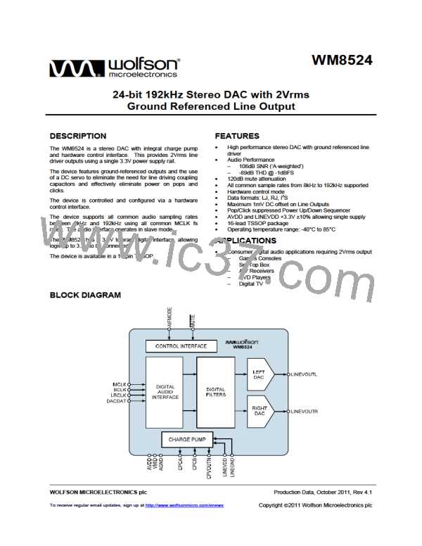
The device is configured according to logic levels applied to the hardware control pins as described in
Table 4.
PIN NAME
M¯¯U¯T¯E¯
PIN
NUMBER
DESCRIPTION
11
Mute Control
0 = Mute
1 = Normal operation
AIFMODE
12
Audio Interface Mode
0 = 24-bit LJ
1 = 24-bit I2S
Z = 24-bit RJ
Table 4 Hardware Control Pin Configuration
MUTE
The M¯¯U¯T¯E¯ pin controls the DAC mute to both left and right channels. When the mute is asserted a
softmute is applied to ramp the signal down in 800 samples. When the mute is de-asserted the signal
returns to full scale in one step.
PD, Rev 4.1, October 2011
15
w

 WOLFSON [ WOLFSON MICROELECTRONICS PLC ]