NE555
Electrical Characteristics (Notes 1, 2) (Continued)
(TA = 25˚C, VCC = +5V to +15V, unless othewise specified)
Parameter
Conditions
Limits
Typ
Units
Min
Max
Output Voltage Drop (Low)
VCC = 15V
ISINK = 10mA
0.1
0.4
2
0.25
0.75
2.5
V
V
V
V
ISINK = 50mA
ISINK = 100mA
ISINK = 200mA
VCC = 5V
2.5
0.15
0.4
ISINK = 8mA
V
V
0.1
0.25
ISINK = 5mA
0.35
Output Voltage Drop (High)
ISOURCE = 200mA, VCC = 15V
ISOURCE = 100mA, VCC = 15V
VCC = 5V
12.5
13.3
3.3
V
12.75
2.75
V
V
300
300
Rise Time of Output
Fall Time of Output
100
100
ns
ns
Note 1: All voltages are measured with respect to the ground pin, unless otherwise specified.
Note 2: Absolute Maximum Ratings indicate limits beyond which damage to the device may occur. Operating Ratings indicate conditions for which the device is func-
tional, but do not guarantee specific performance limits. Electrical Characteristics state DC and AC electrical specifications under particular test conditions which guar-
antee specific performance limits. This assumes that the device is within the Operating Ratings. Specifications are not guaranteed for parameters where no limit is
given, however, the typical value is a good indication of device performance.
Note 3: For operating at elevated temperatures the device must be derated above 25˚C based on a +150˚C maximum junction temperature and a thermal resistance
170˚C/W (S0-8), junction to ambient.
Note 4: Supply current when output high typically
.
and MAX. is 13mA at Vcc=15V.
9mA
Note 5: Tested at V
= 5V and V
= 15V.
CC
CC
Note 6: This will determine the maximum value of R + R for 15V operation. The maximum total (R + R ) is 20MΩ.
A
B
A
B
Note 7: No protection against excessive pin 7 current is necessary providing the package dissipation rating will not be exceeded.
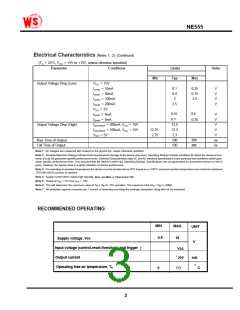
RECOMMENDED OPERATING
MIN
4.5
MAX.
16
UNIT
V
Supply voltage ,Vcc
Input voltage (control,reset,threshold, and trigger
Output current
)
Vcc
+- 200
mA
o
Operating free-air temperature, TA
0
C
7
0
3

 Wing Shing [ WING SHING COMPUTER COMPONENTS ]