W90N745CD/W90N745CDG
6.13 General-Purpose Input/Output
The General-Purpose Input/Output (GPIO) module possesses 31 pins and serves multiple function
purposes. Each port can be configured by software to meet various system configurations and design
requirements. Software must configure each pin before starting the main program. If a pin is not used for
multiplexed functions, the pin can be configured as I/O port
Two extended interrupts nIRQ2 (GPIO0 pin) and nIRQ3 (nWAIT pin) are used the same interrupt request
(channel #31) of AIC. It can be programmed as low/high sensitive or positive/negative edge triggered.
When interrupt #31 assert in AIC, software can poll XISTATUS status register to identify which interrupt
occur.
These 31 IO pins are divided into 7 groups according to its peripheral interface definition.
y
y
y
y
y
y
y
Port0: 5-pin input/output port
Port1: 2-pin input/output port
Port2: 10-pin input/output port
Port3: Reserved
Port4: 1-pin input/output port
Port5: 13-pin input/output port
Port6: Reserved
need updated
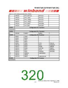
Table 6.13.1 GPIO multiplexed functions table
Configurable Pin Functions
PORT0
AC97_nRESET
nIRQ2
GPIO0
GPIO1
GPIO2
0
1
2
USBPWREN
DTR3
(I²S_MCLK)
AC97_DATAI (I²S_DATAI) PWM0
AC97_DATAO
PWM1
DSR3
(I²S_DATAO)
AC97_SYNC
PWM2
GPIO3
GPIO4
3
4
TXD3
RXD3
(I²S_LRCLK)
AC97_BITCLK
PWM3
(I²S_BITCLK)
PORT1
Configuration Pin Functions
0
GPIO18
GPIO19
-
-
nXDACK
nXDREQ
-
-
1
PORT2
Configuration Pin Functions
0
1
2
3
GPIO20
GPIO21
GPIO22
GPIO23
PHY_RXERR
PHY_CRSDV
PHY_RXD[0]
PHY_RXD[1]
KPCOL0
KPCOL1
KPCOL2
KPCOL3
-
-
-
-
- 314 -

 WINBOND [ WINBOND ]