Preliminary W78E51B
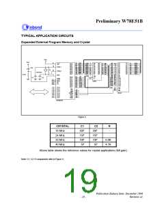
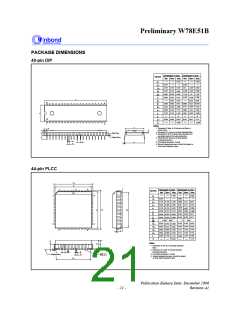
PACKAGE DIMENSIONS
40-pin DIP
Dimension in inch
Dimension in mm
Symbol
A
Nom.
Nom.
Min.
Max. Min.
0.210
Max.
5.334
0.010
0.150
0.016
0.048
0.008
0.254
1
A
0.155
0.018
0.050
0.010
2.055
0.160
0.022
0.054
0.014
2.070
0.610
3.81
3.937 4.064
0.457 0.559
2
A
0.406
1.219
0.203
B
1.27
1.372
0.356
1
B
0.254
c
D
E
D
52.20 52.58
40
21
15.494
13.97
2.794
15.24
13.84
2.54
0.590 0.600
14.986
13.72
0.540
0.090
0.120
0
0.545
0.100
0.550
0.110
1
E
2.286
1
e
0.140 3.048
3.302
0.130
3.556
15
1
E
L
a
15
0
17.01
0.630 0.650
0.670
0.090
16.00
16.51
A
e
S
2.286
1
20
Notes:
E
1. Dimension D Max. & S include mold flash or
tie bar burrs.
S
c
2. Dimension E1 does not include interlead flash.
3. Dimension D & E1 include mold mismatch and
are determined at the mold parting line.
4. Dimension B1 does not include dambar
protrusion/intrusion.
5. Controlling dimension: Inches.
6. General appearance spec. should be based on
final visual inspection spec.
A2
A
Base Plane
1
A
.
L
Seating Plane
B
e1
e
A
a
B 1
44-pin PLCC
H D
D
6
1
44
40
Dimension in inch Dimension in mm
Symbol
A
Nom.
Nom.
Min.
Max. Min.
0.185
Max.
7
39
4.699
0.020
0.145
0.508
A
1
0.150
3.81
0.711
0.457
0.155 3.683
3.937
0.813
0.559
0.356
A2
0.026 0.028 0.032
0.022
0.66
b
b
c
1
0.406
0.016 0.018
H E
GE
E
0.008 0.010 0.014 0.203 0.254
16.46 16.59 16.71
16.46 16.59 16.71
1.27 BSC
0.648 0.653 0.658
0.648 0.653 0.658
0.050 BSC
D
E
e
0.590
0.590
0.680
0.680
14.99 15.49 16.00
0.610 0.630
0.610 0.630
0.690 0.700
17
29
GD
16.00
17.27 17.53 17.78
14.99 15.49
E
G
18
28
D
H
c
17.27
0.700
17.53 17.78
2.54 2.794
0.10
0.690
H
L
y
E
0.090 0.100
0.110 2.296
0.004
L
Notes:
A 2
A
1. Dimension D & E do not include interlead
flash.
2. Dimension b1 does not include dambar
protrusion/intrusion.
q
e
b
A1
3. Controlling dimension: Inches
4. General appearance spec. should be based
on final visual inspection spec.
b 1
Seating Plane
y
G D
Publication Release Date: December 1998
Revision A1
- 21 -

 WINBOND [ WINBOND ]