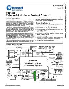
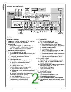
PC97551 Block Diagram
LPC
I/F
Processing
Unit
Reset &
Config
Serial
IRQ
DMA
CR16B Core
SMI
Core Bus
Host
Controlled
Functions
Memory
I/F Functions
Bus
Adapter
CR Access
Bridge
Shared mem.
+ Protection
LPC Bus I/F
RAM
ROM
BIU
Internal Bus
Peripherals
Peripheral Bus
ACB
(X2)
KBC + PM
Host I/F
Timer +
WDG
MSWC
HFCG
PMC
ADC
ICU
USART
KBSCAN
GPIO
PS/2
I/F
Debugger
MFT16
(X2)
MIWU
PWM
DAC
I/F
Valid Battery
+ Oscillator
CLK
External
Memory + I/O
JTAG
32.768 KHz
Features
■ Operation Modes
— IRE - Normal operation mode
— OBD - On-Board Development mode
Embedded Controller
■ CompactRISC CR16B Processing Unit - a 16-bit em-
bedded RISC processor core (the “core”)
■ Used for development in the final system
■ Communicates with debugger via JTAG interface
■ Hardware breakpoint support
■ Internal Memory
— Boot block for core code in 4 Kbytes of ROM
— 4 Kbytes of on-chip RAM with contents protection
— ROM and RAM both can hold code and data
— DEV - Development mode
■ Used in In-System Emulators (ISE) and Applica-
■ Bus Interface Unit (BIU) supporting:
— Up to 2 Mbytes for code and data
tion Development Boards (ADB)
■ Communicates with debugger via JTAG interface
■ On-chip ROM is replaced with off-chip SRAM
■ Cycle-by-cycle compatible with IRE mode
— Provides two chip-selects for flash/ROM and SRAM
devices
— Provides one chip-select for I/O devices
— 8- or 16-bit wide bus
■ LPC System Interface
— Configurable wait states
— 8-bit I/O and 8-bit memory read and write cycles
— 8-bit FWH read and write with wait-sync cycles
— Bootable memory support
— Enhanced performance using fast read cycles
■ Single-cycle, fast-read (word-aligned)
■ Two-byte, burst-read (byte-aligned)
— BIOS sharing with PC host
— Base Address (BADDR) strap to determine the base
address of the Index-Data register pair
— Host-core shared memory access protection
■ Host-controlled with core override
— Serial IRQ (SERIRQ) support
— LPCPD and CLKRUN support
■ 64-Kbyte and 8-Kbyte blocks with independent
Core-Controlled Functions
protection
■ Interrupt Control Unit (ICU)
■ Hardware-protected boot zone for host code
— Download for on-board code updating
■ Host-controlled via LPC
— Non-maskable interrupt input (PFAIL)
— 31 maskable vectored interrupts
— Enable and pending indication for each interrupt
■ Core-controlled via JTAG or serial port
— External memory “power-down” mode
— General-purpose external interrupt inputs through
MIWU
www.winbond.com
2
Revision 1.1

 WINBOND [ WINBOND ]