SVSA2800S Series
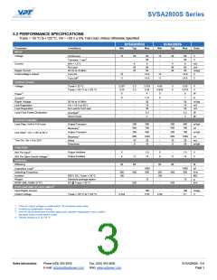
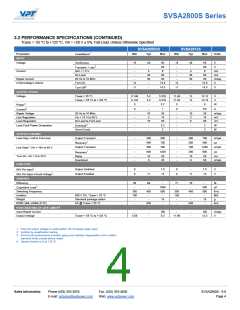
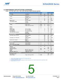
3.2 PERFORMANCE SPECIFICATIONS (CONTINUED)
Tcase = -55 °C to +125 °C, Vin = +28 V ± 5%, Full Load, Unless Otherwise Specified
SVSA2815S
3
Parameter
INPUT
Min
Typ
Max
Units
Conditions
Voltage
Continuous
15
-
28
-
50
80
V
2
V
Transient, 1 sec
INH < 1.5 V
No Load
Current
-
4
6
mA
mA
mApp
V
-
45
30
-
60
Ripple Current
20 Hz to 10 MHz
Turn-On
-
50
Undervoltage Lockout
12
11
14.8
14.5
2
-
V
Turn-Off
OUTPUT STATIC
Voltage
Tcase = 25 °C
14.85
14.775
0
15
15
-
15.15
15.225
6
V
Tcase = -55 °C to +125 °C
V
4
W
Power
4
0
-
-
10
2
5
-
0.4
30
15
50
3
A
Current
Ripple Voltage
20 Hz to 10 MHz
mVpp
mV
mV
W
Line Regulation
Vin = 15 V to 50 V
No Load to Full Load
-
Load Regulation
-
2
Load Fault Power Dissipation
-
Overload
Short Circuit
-
-
3
W
OUTPUT DYNAMIC
Load Step, Half to Full Load
Output Transient
-
-
300
200
700
400
mVpk
µs
1
Recovery
2
Output Transient
-
700
1300
mVpk
Line Step , Vin = 16V to 40 V
1
-
-
-
200
10
0
600
20
µs
Recovery
Turn-On, Vin = 0 to 28 V
Delay
ms
Overshoot
50
mVpk
FUNCTION
2
Output Inhibited
Output Enabled
0
9
-
1.5
13
V
V
INH Pin Input
2
11
INH Pin Open Circuit Voltage
GENERAL
Efficiency
72
78
-
500
500
-
%
2
-
350
100
-
-
450
-
µF
kHz
MΩ
g
Capacitive Load
Switching Frequency
Isolation
500 V DC, Tcase = 25 °C
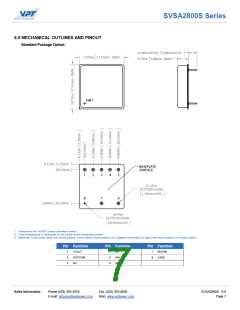
Standard package option
SF @ Tcase = 55 °C
Weight
-
15
-
MTBF (MIL-HDBK-217F)
-
830
kHr
3
POST-RAD END-OF-LIFE LIMITS
Input Ripple Current
-
-
-
100
mApp
V
Output Voltage
Tcase = -55 °C to +125 °C
14.565
15.4
1. Time for output voltage to settle within 1% of steady-state value
2. Verified by qualification testing
3. End-of-Life performance includes aging and radiation degradation and is within standard limits except where noted
4. Derate linearly to 0 at 135°C
Sales Information
Phone:(425) 353-3010
Fax: (425) 353-4030
SVSA2800S - 9.0
Page 5
E-mail: vptsales@vptpower.com
Web: www.vptpower.com

 VPT [ VPT, Inc. ]