UFB200FA40P
Insulated Ultrafast
Rectifier Module, 230 A
Vishay High Power Products
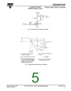
V
R = 200 V
0.01 Ω
L = 70 µH
D.U.T.
D
dIF/dt
adjust
IRFP250
G
S
Fig. 9 - Reverse Recovery Parameter Test Circuit
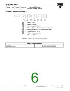
(3)
trr
IF
ta
tb
0
(4)
Qrr
(2)
IRRM
0.5 IRRM
(5)
dI(rec)M/dt
0.75 IRRM
dIF/dt
(1)
(4) Qrr - area under curve defined by trr
and IRRM
(1) dIF/dt - rate of change of current
through zero crossing
trr x IRRM
(2) IRRM - peak reverse recovery current
Qrr
=
2
(3) trr - reverse recovery time measured
from zero crossing point of negative
going IF to point where a line passing
through 0.75 IRRM and 0.50 IRRM
extrapolated to zero current.
(5) dI(rec)M/dt - peak rate of change of
current during tb portion of trr
Fig. 10 - Reverse Recovery Waveform and Definitions
Document Number: 94088
Revision: 25-Apr-08
For technical questions, contact: ind-modules@vishay.com
www.vishay.com
5

 VISHAY [ VISHAY ]