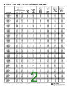
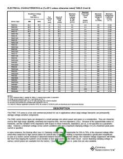
ELECTRICAL CHARACTERISTICS at (T =25°C unless otherwise noted) TABLE (Cont’d)
A
Maximum
Breakdown Voltage
V(BR)
Maximum
Reverse
Leakage
at VWM
ID (µA)
(NOTE3)
Peak Pulse
Current
IPPM
Maximum
Clamping
Voltage at
IPPM
Maximum
Temperature
Coefficient
of V(BR)
Volts (NOTE 1)
Test
Current
at IT
Stand-off
Voltage
VWM
(Amps)
(NOTE 2)
VC (Volts)
(% / C)
Device Type
MIN
MAX
(Volts)
(mA)
P6KE91A
P6KE100
P6KE100A
P6KE110
P6KE110A
P6KE120
P6KE120A
P6KE130
P6KE130A
P6KE150
P6KE150A
P6KE160
P6KE160A
P6KE170
P6KE170A
P6KE180
P6KE180A
P6KE200
P6KE200A
P6KE220
P6KE220A
P6KE250
P6KE250A
P6KE300
P6KE300A
P6KE350
P6KE350A
P6KE400
P6KE400A
P6KE440
P6KE440A
86.5
90.0
95.0
99.0
105
108
114
117
124
135
143
144
152
153
162
162
171
180
190
198
209
225
237
270
285
315
333
360
380
396
418
95.5
110
105
121
116
132
126
143
137
165
158
176
168
187
179
198
189
220
210
242
231
275
263
330
315
385
368
440
420
484
462
1.0
1.0
1.0
1.0
1.0
1.0
1.0
1.0
1.0
1.0
1.0
1.0
1.0
1.0
1.0
1.0
1.0
1.0
1.0
1.0
1.0
1.0
1.0
1.0
1.0
1.0
1.0
1.0
1.0
1.0
1.0
77.8
81.0
85.5
89.2
94.0
97.2
102
105
111
5.0
5.0
5.0
5.0
5.0
5.0
5.0
5.0
5.0
5.0
5.0
5.0
5.0
5.0
5.0
5.0
5.0
5.0
5.0
5.0
5.0
5.0
5.0
5.0
5.0
5.0
5.0
5.0
5.0
5.0
5.0
4.8
4.2
4.4
3.8
3.9
3.5
3.6
3.2
3.4
2.8
2.9
2.6
2.7
2.5
2.6
2.3
2.4
2.1
2.2
1.7
1.8
1.7
1.7
1.4
1.4
1.2
1.2
1.0
1.1
0.95
1.0
125
144
137
158
152
173
165
187
179
215
207
230
219
244
234
258
246
287
274
344
328
360
344
430
414
504
482
574
548
631
602
0.106
0.106
0.106
0.107
0.107
0.107
0.107
0.107
0.107
0.108
0.108
0.108
0.108
0.108
0.108
0.108
0.108
0.108
0.108
0.108
0.108
0.110
0.110
0.110
0.110
0.110
0.110
0.110
0.110
0.110
0.110
121
128
130
136
138
145
146
154
162
171
175
185
202
214
243
256
284
300
324
342
356
376
NOTES:
(1) V(BR) measured after IT applied for 300µs, IT=square wave pulse or equivalent
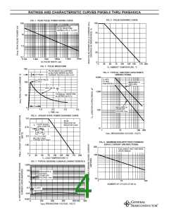
(2) Surge current waveform per Fig. 3 and derate per Fig. 2
(3) For bidirectional types with VWM of 10 volts and less, the ID limit is doubled
(4) All terms and symbols are consistent with ANSI/IEEE C62.35
+UL listed for Telecom application protection 497B, file number E136766 for both uni-directional and bi-directional devices
DESCRIPTION
This P6KE TVS series is a low cost commercial product for use in applications where large voltage transients can permanently
damage voltage-sensitive components.
The P6KE series device types are designed in a small package size where power and space is a consideration. They are character-
ized by their high surge capability, extremely fast response time, and low impedance, (Ron). Because of the unpredictable nature of
transients, and the variation of the impedance with respect to these transients, impedance, per se, is not specified as a parametric
value. However, a minimum voltage at low current conditions (BV) and a maximum clamping voltage (Vc) at a maximum peak pulse
current is specified.
In some instances, the thermal effect (see Vc Clamping Voltage) may be responsible for 50% to 70%. of the observed voltage differ-
ential when subjected to high current pulses for several duty cycles, thus making a maximum impedance specification insignificant.
In case of a severe current overload or abnormal transient beyond the maximum ratings, the Transient Voltage Suppressor will initially
fail 'short' thus tripping the system's circuit breaker or fuse while protecting the entire circuit. Curves depicting clamping voltage vs.
various current pulses are available from the factory. Extended power curves vs. pulse time are also available.

 VISHAY [ VISHAY ]