2322 59. .....
Varistors
Vishay BCcomponents
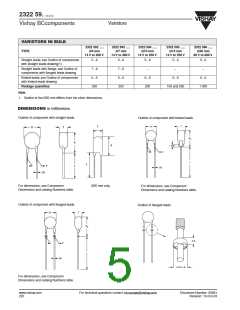
TAPING DATA (based on “IEC 60286-2”)
DIMENSIONS
NOMINAL (mm)
TOLERANCE
(mm)
SYMBOL
PARAMETER
REMARKS
D
T
body diameter
total thickness
see Component Dimensions table
see Component Dimensions table
see Component Dimensions table
see Component Dimensions table
see Component Dimensions table
A0; A
∅d
F
mounting height
lead diameter
lead to lead distance
component pitch
guaranteed between component and tape
P
12.7 or 25.4
12.7
±1.0
±0.3
P0
P1
∆p
∆h
W
feed hole pitch
cumulative pitch error ±1
feed hole centre to lead centre
component alignment
component alignment
tape width
3.85 or 8.95
0.0
±0.7
guaranteed between component and tape
±1.3
0.0
±2.0
18.0
+1.0/−0.5
W0
W1
W2
H
hold down tape width
hole position
≥12.5
≤3.0
9.0
±0.5
hold down tape position
height between component
and tape centre
18.0
20.0
+2.0/−0.0
+2.0/−0.0
±0.5
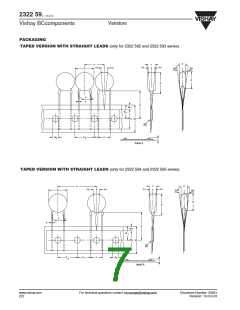
straight lead version 2322 594 and 2322 595
straight lead version 2322 592 and 2322 593
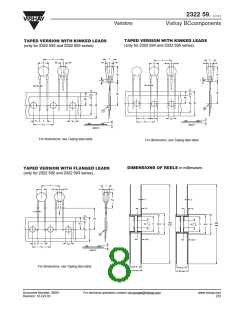
flanged and kinked lead versions
H0
D0
t
lead-wire flange height
feed hole diameter
total tape thickness
16.0 or 18.25
4.0
±0.2
≤1.4
with cardboard tape 0.5 ±0.1 mm
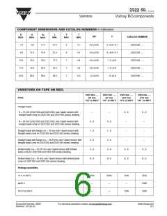
VARISTORS ON TAPE IN AMMOPACK
2322 592 .....
2322 593 .....
2322 594 .....
2322 595 .....
∅
∅
∅
∅
14 MM
TYPE
MM
7 MM
10 MM
14 V TO 460 V
14 V TO 460 V
14 V TO 550 V
14V TO 550 V
Straight leads;
H = 18 or 20 mm; see Taped version
with straight leads (only for 2322 592
and 2322 593 series) and Taped
version with straight leads (only for
2322 594 and 2322 595 series)
drawings
0...7
0...7
0...7
0...7
Straight leads with flange;
H0 = 16 mm; see Taped version with
flanged leads (onlt for 2322 592 and
2322 593 series) drawing
1...7
2...7
3...7
8...7
1...7
2...7
3...7
8...7
−
−
Straight leads with flange;
H0 = 18.25 mm; see Taped version
with flanged leads (onlt for 2322 592
and 2322 593 series) drawing
−
−
Kinked leads;
H0 = 18.25 mm; see Taped version
with kinked leads (only for 2322 594
and 2322 595 series) drawing
3...7
8...7
3...7
8...7
Kinked leads;
H0 = 16 mm; see Taped version with
kinked leads (only for 2322 592 and
2322 593 series) drawing
Package quantities
14 to 175 V
1500
1000
−
1500
1000
−
750
−
750
−
230 to 460 V
230 to 300 V
320 to 550 V
600
500
600
500
−
−
www.vishay.com
224
For technical questions contact: nlr.europe@vishay.com
Document Number: 29081
Revision: 10-Oct-03

 VISHAY [ VISHAY ]