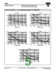
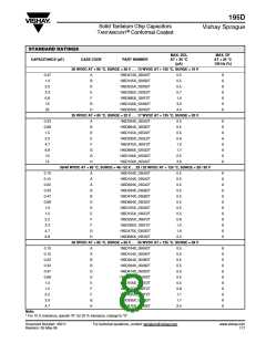
195D
Solid Tantalum Chip Capacitors
TANTAMOUNT Conformal Coated
Vishay Sprague
®
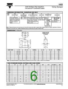
ORDERING INFORMATION - EUROPEAN USE ONLY
195D
106
X0
004
D
2
T
TYPE
CAPACITANCE
CAPACITANCE
TOLERANCE
DC VOLTAGE RATING
AT + 85 °C
CASE CODE TERMINATION
PACKAGING
This is expressed in
picofarads. The first two
digits are the significant
figures. The third is the
number of zeros to
follow.
X0 = 20 %
X9 = 10 %
This is expressed in volts. See Ratings Style 2 is
To complete the three-digit and Case standard
T = Tape and Reel
180 mm Reel
block, zeros precede the
voltage rating. A decimal
point is indicated by an “R”
(6R3 = 6.3 V).
Codes Table 2 = Solderable
standard
Coating
See Tape and Reel
4 = Gold Plated Specifications.
8 = Solder
Plated
(60/40)
Special Order
Note: Preferred tolerance and reel sizes are in bold. We reserve the right to supply higher voltage ratings and tighter capacitance tolerance
capacitors in the same size. Voltage substitutions will be marked with the higher voltage rating.
DIMENSIONS in millimeters
W
Tantalum wire Nib
identifies Anode
(+) terminal
C
B
L
J
J
D
A
H
CASE CODE
L
0.3
W
0.3
1.5
H (MAX.)
A
0.3
0.7
B
0.3
1.6
C (MIN.)
A
B
D
E
F
2.8 0.2
4.2 0.2
4.2 0.2
5.5
1.4
1.6
1.6
1.7
2.0
2.8
3.0
0.3
0.3
0.5
0.8
0.8
0.8
0.8
1.4
2.1
2.1
3.3
2.6
3.7
0.8
0.8
1.0
1.0
1.0
1.0
2.5
2.5
3.2
3.6
4.5
5.0
5.0
G
H
7.0
7.8
Note: The anode termination (D less B) will be a minimum of 0.010 (0.25), C Case = 0.005 (0.131) minimum
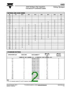
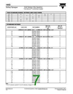
195D STANDARD RANGE, RATINGS AND CASE CODES
µF
0.10
0.15
0.22
0.33
0.47
0.68
1.0
2 V
4 V
6.3 V
10 V
15 V
20 V
25 V
35 V/40 V
50 V
A
A
A
A
B
B
D
D
E
F
A
B
A
B
B
A
A
B
B
A
B
D
D
A
B
E
1.5
A
B
D
E
F
2.2
A
B
D
D
E
F
3.3
A
A
A
A
D
E
F
G
H
4.7
D
E
F
G
G
G
H
6.8
D
E
F
10
F
Document Number: 40011
Revision: 05-May-08
For technical questions, contact: tantalum@vishay.com
www.vishay.com
115

 VISHAY [ VISHAY ]