V23990-P546-*3*-PM
Output Inverter
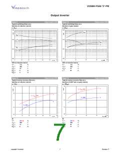
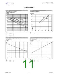
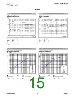
Figure 25
Output inverter IGBT
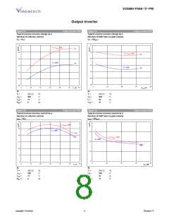
Figure 26
Output inverter IGBT
Gate voltage vs Gate charge
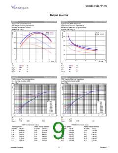
Safe operating area as a function
of collector-emitter voltage
IC = f(VCE
)
VGE = f(QGE
18
)
103
16
14
12
10
8
102
120V
480V
10uS
1mS
100uS
100mS
101
DC
10mS
100
6
4
10-1
2
0
0
40
80
120
160
200
240
Q g (nC)
100
V CE (V)
103
102
101
At
At
IC
=
D =
30
A
single pulse
Th
=
80
ºC
V
VGE
Tj =
=
15
Tjmax
ºC
Figure 27
Output inverter IGBT
Figure 28
Output inverter IGBT
Short circuit withstand time as a function of
gate-emitter voltage
Typical short circuit collector current as a function of
gate-emitter voltage
tsc = f(VGE
)
VGE = f(QGE
)
14
500
12
10
8
400
300
200
100
6
4
2
0
0
10
11
12
13
14
15
12
14
16
18
20
V GE (V)
V GE (V)
At
At
VCE
=
VCE
≤
600
175
V
600
175
V
Tj ≤
Tj =
ºC
ºC
copyright Vincotech
11
Revision: 4

 VINCOTECH [ VINCOTECH ]