10-FZ06NBA050SA-P915L33
datasheet
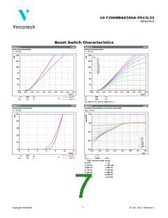
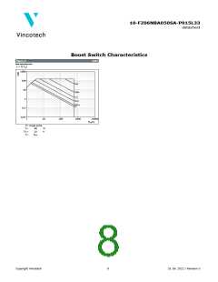
Boost Switch Characteristics
figure 1.
IGBT
figure 2.
IGBT
Typical output characteristics
Typical output characteristics
IC = f(VCE
)
IC = f(VCE)
150
150
VGE
:
6 V
7 V
125
100
75
50
25
0
125
100
75
50
25
0
8 V
9 V
10 V
11 V
12 V
13 V
14 V
15 V
16 V
0,0
0,5
1,0
1,5
2,0
2,5
3,0
3,5
4,0
4,5
0,0
0,5
1,0
1,5
2,0
2,5
3,0
3,5
4,0
4,5
V
CE(V)
VCE(V)
tp
=
tp
=
250
15
μs
V
250
150
μs
°C
25 °C
Tj:
VGE
=
Tj =
150 °C
VGE from 6 V to 16 V in steps of 1 V
figure 3.
IGBT
figure 4.
IGBT
Typical transfer characteristics
Transient thermal impedance as a function of pulse width
IC = f(VGE
)
Zth(j-s) = f(tp)
1
50
10
40
30
20
10
0
10
-1
10
0,5
0,2
0,1
-2
10
0,05
0,02
0,01
0,005
0
-3
0
0
10
-5
-4
10
-3
10
-2
10
-1
10
0
10
1
10
2
2
4
6
8
10
12
10
10
tp(s)
V
GE(V)
tp
VCE
=
=
250
10
μs
V
D =
tp / T
1,059
25 °C
Tj:
150 °C
Rth(j-s) =
K/W
IGBT thermal model values
R (K/W)
τ (s)
1,11E-01
3,60E-01
3,77E-01
1,24E-01
4,58E-02
4,19E-02
1,12E+00
1,48E-01
4,74E-02
7,68E-03
6,49E-04
1,61E-04
Copyright Vincotech
7
31 Jul. 2022 / Revision 3

 VINCOTECH [ VINCOTECH ]