TEA2025
LINEAR INTEGRATED CIRCUIT
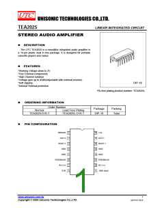
APPLICATION INFORMATION
Input Capacitor
Input capacitor is PNP type allowing source to be referenced to ground. In this way no input coupling capacitor is
required. However, a series capacitor (0.22 uF)to the input side can be useful in case of noise due to variable
resistor contact.
Bootstrap
The bootstrap connection allows to increase the output swing. The suggested value for the bootstrap capacitors
(100uF) avoids a reduction of the output signal also at low frequencies and low supply voltages.
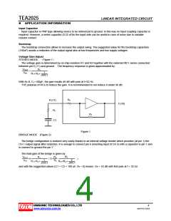
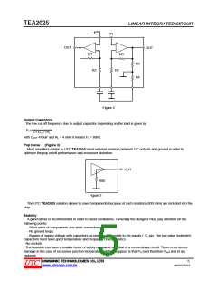
Voltage Gain Adjust
STEREO MODE (Figure 1)
The voltage gain is determined by on-chip resistors R1 and R2 together with the external RfC1 series connected
between pin 6 (11) and ground. The frequency response is given approximated by:
VOUT
VIN
R1
=
1
R
f
R
+
+
2
JWC1
With Rf=0, C1=100μF, the gain results 46 dB with pole at f=32 Hz.
THE purpose of Rf is to reduce the gain. It is recommended to not reduce it under 36 dB.
R2
6 (11)
Rf
2 (15)
R1
C1
Figure 1
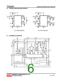
BRIDGE MODE (Figure 2)
The bridge configuration is realized very easily thanks to an internal voltage divider which provides (at pin 1) the
CH 1 output signal after reduction. It is enough to connect pin 6 (inverting input of CH 2) with a capacitor to pin 1 and
to connect to ground the pin 7.
The total gain of the bridge is given by:
and with the suggested values (C1 = C2 = 100 uF, Rf = 0) means: Gv = 52 dB with first pole at f = 32 Hz
UNISONIC TECHNOLOGIES CO., LTD
4
www.unisonic.com.tw
QW-R107-033.B

 UTC [ Unisonic Technologies ]