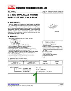
TDA7377
LINEAR INTEGRATED CIRCUIT
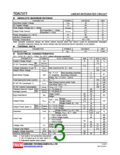
ABSOLUTE MAXIMUM RATINGS
PARAMETER
SYMBOL
VOP
RATINGS
18
UNIT
V
Operating Supply Voltage
DC Supply Voltage
VS
28
V
Peak Supply Voltage (for t = 50ms)
VS(PEAK)
50
V
not Repetitive t = 100µs
4.5
A
Output Peak Current
IO(PEAK)
Repetitive f >10Hz
3.5
A
Power Dissipation (TC= 85°C)
Junction Temperature
PD
TJ
36
W
°C
°C
+150
-40~+150
Storage Temperature
TSTG
Note: Absolute maximum ratings are those values beyond which the device could be permanently damaged.
Absolute maximum ratings are stress ratings only and functional device operation is not implied.
THERMAL DATA
PARAMETER
SYMBOL
RATINGS
1.8
UNIT
°C/W
Junction to Case
θJC
ELECTRICAL CHARACTERISTICS
(VS = 14.4V; RL = 4ꢀ; f = 1 KHz; Ta =25°C, unless otherwise specified)
PARAMETER
SYMBOL
VS
TEST CONDITIONS
MIN
8
TYP
MAX UNIT
Supply Voltage Range
18
V
IN
VI(ST-BY)
1.5
ST-BY Threshold Voltage
V
OUT VO(ST-BY)
3.5
Voltage Saturation on pin 10
Output Offset Voltage
VSAT Sink Current at Pin 10 = 1mA
VO(OFF)
0.7
V
150
mV
Non Inverting Channels
Inverting Channels
2
5
Rg = 0; S.E.
”A” weighted,
µV
Input Noise Voltage
eN
Bridge, Rg = 0; 22Hz ~ 22KHz
RL = ∞
3.5
µV
mA
mA
µA
µA
µA
µA
Total Quiescent Drain Current
ST-BY Pin Current(pin 7)
IQ
150
5
Max Driving Current Under Fault
Play Mode Vpin7 = 5V
IST-BY
50
ST-BY Current Consumption
Clipping Detector Output OFF
IST-BY VST-BY = 0 ~ 1.5V
ICD(OFF) d = 1% (Note 2)
ICD(ON) d = 5% (Note 2)
100
90
160
30
Average Current
ON
Single Ended
20
10
18
5.5
Input Impedance
RIN
Kꢀ
Bridge
15
Bridge
20
THD = 10%;
RL = 4ꢀ
Output Power
POUT
W
Single Ended
6
Single Ended, RL = 2ꢀ
10
Max
PO(MAX) VS = 14.4V, Bridge
PO(EIAJ) VS = 13.7V, Bridge
31
27
35
W
W
Output Power (Note 3)
Distortion
EIAJ
30
Single Ended, POUT=0.1~4W
0.02
0.03
70
THD RL = 4ꢀ
%
Bridge, POUT = 0.1 ~ 10W
f = 1KHz Single Ended
0.3
dB
dB
dB
dB
dB
dB
dB
dB
dB
f = 10KHz Single Ended
f = 1KHz Bridge
f = 10KHz Bridge
Single Ended
60
Cross Talk
CT
55
60
20
26
19
25
21
27
Voltage Gain
GV
GV
Bridge
Voltage Gain Match
0.5
Supply Voltage Rejection
Stand-by Attenuation
SVR Rg = 0; f = 300Hz
AST-BY PO = 1W
50
80
90
Note: 1. See built-in S/C protection description
2. Pin 10 Pulled-up to 5V with 10Kꢀ; RL = 4ꢀ
3. Saturated square wave output.
UNISONIC TECHNOLOGIES CO., LTD
3 of 8
QW-R107-064.A
www.unisonic.com.tw

 UTC [ Unisonic Technologies ]