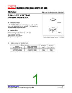
TDA2822
LINEAR INTEGRATED CIRCUIT
ꢀ
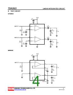
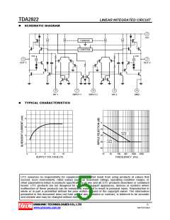
SCHEMATIC DIAGRAM
2
Vcc
I source
CONTROL
Vcc
Vcc
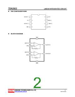
1
3
OUT 1
OUT 2
8
7
6
5
4
NF 1
INPUT 1
INPUT 2
NF 2
GND
ꢀ
TYPICAL CHARACTERISTICS
8
6
4
2
0
10
20
30
40
C1=C2
=22 µF
C1=C2
=100 µF
0
4
8
12
16
10
30
100
300
1000
3000
SUPPLY VOLTAGE (V)
FREQUENCY (Hz)
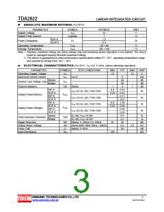
UTC assumes no responsibility for equipment failures that result from using products at values that
exceed, even momentarily, rated values (such as maximum ratings, operating condition ranges, or
other parameters) listed in products specifications of any and all UTC products described or contained
herein. UTC products are not designed for use in life support appliances, devices or systems where
malfunction of these products can be reasonably expected to result in personal injury. Reproduction in
whole or in part is prohibited without the prior written consent of the copyright owner. The information
presented in this document does not form part of any quotation or contract, is believed to be accurate
and reliable and may be changed without notice.
UNISONIC TECHNOLOGIES CO., LTD
5
www.unisonic.com.tw
QW-R107-006.E

 UTC [ Unisonic Technologies ]