NE555
LINEAR INTEGRATED CIRCUIT
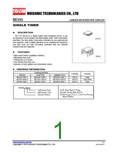
ABSOLUTE MAXIMUM RATINGS
PARAMETER
SYMBOL
VCC
RATINGS
16
UNIT
V
Supply Voltage
Power Dissipation
PD
600
mW
℃
Junction Temperature
Operating Temperature
Storage Temperature
TJ
+125
℃
TOPR
TSTG
-20 ~ +85
-40 ~ +150
℃
Note: Absolute maximum ratings are those values beyond which the device could be permanently damaged.
Absolute maximum ratings are stress ratings only and functional device operation is not implied.
ELECTRICAL CHARACTERISTICS (VCC=5 ~ 15V, Ta=25℃, unless otherwise specified.)
PARAMETER
SYMBOL
VCC
TEST CONDITIONS
MIN
4.5
TYP
MAX UNIT
Supply Voltage
16
6
V
mA
mA
%
VCC=5V, RL=∝
VCC=15V, RL=∝
RA=1k ~ 100kΩ
3
Supply Current (Note 1)
ICC
7.5
1.0
2.25
50
15
3.0
Monostable
Astable
Initial Accurary (Note 2)
ACCUR
%
Monostable
ppm/°C
Drift with Temperature
Drift with Supply Voltage
Control Voltage
Δt/ΔT
Δt/ΔVCC
VC
C=0.1μF
Astable
150
0.1
ppm/°C
%/V
%/V
V
Monostable
Astable
0.5
0.3
VCC=15V
VCC=5V
VCC=15V
VCC=5V
9.0
2.6
10.0
3.33
10.0
3.33
0.1
11.0
4.0
V
V
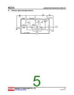
Threshold Voltage
Threshold Current(Note 3)
Trigger Voltage
VTH
ITH
V
0.25
2.2
5.6
2.0
1.0
0.4
μA
V
VCC=5V
1.1
4.5
1.67
5
VTR
V
CC=15V
V
Trigger Current
Reset Voltage
Reset Current
ITR
VRST
IRST
VTR=0
0.01
0.7
μA
V
0.4
0.1
mA
VCC=15V
ISINK=10mA
ISINK=50mA
VCC=5V
0.06
0.3
0.25
0.75
V
V
Low Output Voltage
High Output Voltage
VOL
ISINK=5mA
0.05
12.5
0.35
V
VCC=15V
ISOURCE=200mA
ISOURCE=100mA
V
V
VOH
12.75 13.3
VCC=5V, ISOURCE=100mA
2.75
3.3
100
100
20
V
Rise Time of Output
tR
tF
ns
ns
nA
Fall Time of Output
Discharge Leakage Current
ILKG
100
Note 1: Supply current when output high typically 1mA less at VCC=5V.
Note 2: Tested at VCC=5.0V and VCC=15V.
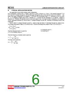
Note 3: This will determine the maximum value of RA+RB for 15V operation, The maximum total is R=20MΩ, and for
5V operation the maximum total is R=6.7MΩ.
UNISONIC TECHNOLOGIES CO., LTD
4 of 8
www.unisonic.com.tw
QW-R106-001,F

 UTC [ Unisonic Technologies ]