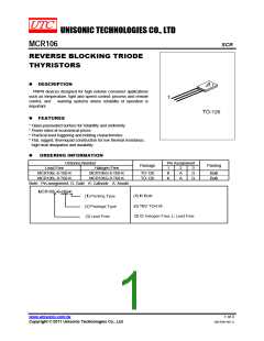
MCR106
SCR
ABSOLUTE MAXIMUM RATINGS (TJ=25℃, unless otherwise specified)
PARAMETER SYMBOL
RATINGS
400
UNIT
MCR106-6
MCR106-8
V
V
A
A
Peak Repetitive Forward and Reverse Blocking
Voltage (Note 1) (TJ=110℃, RGK=1kΩ)
V
DRM, VRRM
600
RMS Forward Current (All conduction Angles)
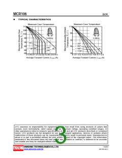
Average Forward Current (TC=93℃or TA=30℃)
IT(RMS)
IT(AV)
4
2.55
Peak Non-repetitive Surge Current
(1/2 Cycle, 60Hz, TJ=-40 ~ +110℃)
ITSM
25
A
Circuit Fusing Considerations (t=8.3 ms)
Peak Gate Power
I2t
2.6
A2S
W
PGM
0.5
Average Gate Power
PG(AV)
IGM
0.1
W
Peak Forward Gate Current
Peak Reversed Gate Voltage
Mounting Torque (Note 2)
Junction Temperature
0.2
A
VRGM
6
6
V
In. lb.
℃
TJ
+110
℃
Storage Temperature
TSTG
-40 ~ +150
Note 1. VDRM and VRRM for all types can be applied on a continuous basis. Ratings apply for zero or negative gate
voltage; however, positive gate voltage shall not be applied concurrent with negative potential on the anode.
Blocking voltages shall not be tested with a constant current source such that the voltage of the devices are
exceeded.
2. Torque rating applies with use of compression washer (B52200-F006 or equivalent). Mounting torque in
excess of 6 in. lb. does not appreciably lower case-to-sink thermal resistance. Anode lead and heatsink
contact pad are common. For soldering purposes (either terminal connection or device mounting), soldering
temperatures shall not exceed +200℃. For optimum results, an activated flux (oxide removing) is
recommended.
3. Absolute maximum ratings are those values beyond which the device could be permanently damaged.
Absolute maximum ratings are stress ratings only and functional device operation is not implied.
THERMAL DATA
PARAMETER
SYMBOL
θJA
RATINGS
UNIT
℃/W
℃/W
Junction to Ambient
Junction to Case
75
3
θJC
ELECTRICAL CHARACTERISTICS (TC=25℃ and RGK=1000 Ω, unless otherwise specified)
PARAMETER SYMBOL TEST CONDITIONS MIN TYP MAX UNIT
Peak Forward or Reverse Blocking
TJ=25℃
10
200
2
μA
μA
V
I
DRM,IRRM
TJ=100℃
Current (VAK=Rated VDRM or VRRM
)
Forward “On” Voltage (ITM=4A peak)
Gate Trigger Current (continuous DC)
(Note)
VTM
V
AK=7V, RL=100Ω
200
500
1
IGT
μA
VAK=7V, RL=100Ω, TC=-40℃
VAK=7V, RL=100Ω, TC=25℃
Gate Trigger Voltage (continuous DC)
Gate Non-Trigger Voltage
Holding Current
VGT
VGD
IH
V
V
VAK=Rated VDRM, RL=100Ω, TJ=110℃
0.2
VAK=7V, TC=25 ℃
TJ=110℃
5
mA
V/μs
Forward Voltage Application Rate
dv/dt
10
Note: RGK current is not included in measurement.
UNISONIC TECHNOLOGIES CO., LTD
2 of 3
QW-R301-001.C
www.unisonic.com.tw

 UTC [ Unisonic Technologies ]