UTCLM78XX LINEAR INTEGRATED CIRCUIT
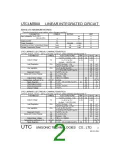
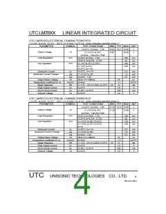
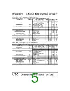
UTC LM7824 ELECTRICAL CHARACTERISTICS
( VI=33V, Io=0.5A, Tj= 0°C - 12°C, C1=0.33uF, Co=0.1uF, unless otherwise specified )(Note 1)
PARAMETER
SYMBOL
TEST CONDITIONS
MIN TYP MAX UNIT
Tj=25°C, IO=5mA - 1.0A
23.04 24.0 24.96
V
Output Voltage
Load Regulation
Vo
∆Vo
VI =27V to 38V,IO=5mA - 1.0A 22.80
Tj=25°C,IO=5mA - 1.5A
Tj=25°C,IO=0.25A - 0.75A
VI =27V to 38V,Tj=25°C
VI =27V to 38V,Tj=25°C,Io=1A
Tj=25°C, IO=<1A
VI =28V to 38V
IO=5mA - 1.0A
10Hz<=f<=100kHz
Io=5mA
VI =28V - 38V,f=120Hz,Tj=25°C
Tj=25°C
VI=35V, Tj=25°C
Tj=25°C
25.20
240
120
240
240
8.0
V
mV
mV
mV
mV
mA
mA
mA
µV
mV/°C
dB
A
mA
V
Line regulation
∆Vo
Quiescent Current
Quiescent Current Change
Iq
∆Iq
∆Iq
VN
∆Vo/∆T
RR
IPK
ISC
Vd
1.0
0.5
Output Noise Voltage
Temperature coefficient of Vo
Ripple Rejection
170
-2.8
66
50
Peak Output Current
Short-Circuit Current
Dropout Voltage
1.8
250
2.0
Note 1: The Maximum steady state usable output current are dependent on input voltage, heat sinking, lead length
of the package and copper pattern of PCB. The data above represents pulse test conditions with junction
temperatures specified at the initiation of test.
Note 2: Power dissipation<0.5W
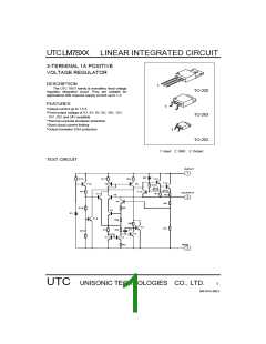
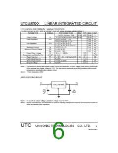
APPLICATION CIRCUIT
Vi
Vo
1
3
UTC LM78XX
2
C1
C0
0.1
0.33
µ
F
µF
Note 1: To specify an output voltage, substitute voltage value for "XX".
Note 2: Bypass capacitors are recommended for optimum stability and transient response and should be located as
close as possible to the regulators.
UTC UNISONIC TECHNOLOGIES CO., LTD.
6
QW-R101-006,C

 UTC [ Unisonic Technologies ]