CAM-M8 - Data Sheet
Parameter
Symbol
Module
Min
Typ
30
Max
Units Condition
SW backup current
I_SWBCKP
CAM-M8Q
µA
µA
V
VCC = 3.0 V
VCC = 3.0 V
CAM-M8C
105
10
Input pin voltage range
Vin
All
All
All
All
All
-0.5
VCC_IO+0.5
0.2*VCC_IO
VCC_IO+0.5
0.4
Digital IO Pin Low level input voltage Vil
Digital IO Pin High level input voltage Vih
Digital IO Pin Low level output voltage Vol
0
V
0.7*VCC_IO
V
V
Iol = 4 mA
Ioh = 4 mA
Digital IO Pin High level output
voltage
Voh
VCC_IO - 0.4
V
Pull-up resistor for RESET_N
(Internal)
Rpu
All
11
kΩ
Receiver Chain Noise Figure 11
NFtot
Topr
All
All
3.5
dB
°C
Operating temperature
–40
85
Table 8: Operating conditions
☞
Operation beyond the specified operating conditions can affect device reliability.
4.3 Indicative power requirements
Table 9 lists examples of the total system supply current for a possible application.
☞
The values in Table 9 are provided for customer information only, as an example of typical power
requirements. Values are characterized on samples; actual power requirements can vary
depending on FW version used, external circuitry, the number of SVs tracked, signal strength,
type of start as well as time, duration and conditions of test.
Parameter
Symbol
Module
Typ
Typ
Max Units
GPS / QZSS / SBAS & GLONASS GPS / QZSS / SBAS
12
Max. supply current
Average supply current
Iccp
All
71
mA
mA
mA
mA
mA
mA
mA
13, 14
15
Icc Acquisition
CAM-M8Q 30
CAM-M8C 32
CAM-M8Q 28
CAM-M8C 28
CAM-M8Q 10.9
CAM-M8C 10.1
26
26
Icc Tracking
(Continuous mode)
23
23
Icc Tracking
(Power Save mode /
1 Hz)
10.4
9.6
Table 9: Indicative power requirements at 3.0 V
☞
☞
For more information about power requirements, see the CAM-M8 Hardware Integration Manual
[1].
For more information on how to noticeably reduce current consumption, see the Power
Management Application Note [5]).
10 If VCC or VCC_IO is 0V there should not be any voltage applied to any I/O (Including RESET_N)
11 Only valid for the GPS band
12
Use this figure to dimension maximum current capability of power supply. Measurement of this parameter with 1 Hz
bandwidth.
13 Use this figure to determine required battery capacity.
14 Simulated GNSS constellation using power lever of –130 dBm. VCC = 3.0 V
15 Average current from start-up until the first fix.
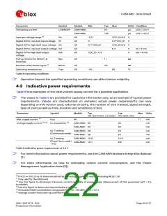
UBX-15031574 - R04
Production Information
Page 22 of 31

 U-BLOX [ u-blox AG ]