CAM-M8 - Data Sheet
1.19 Antenna
The CAM-M8 concurrent GNSS modules are designed with integrated GNSS chip antenna.
Optionally, the CAM-M8 series modules can be connected to an external GNSS antenna.
☞
Because the customer PCB is used as a part of antenna, some important PCB layout design rules
should be followed in order to maintain good performance of the on-board GNSS chip antenna.
For more information, see the CAM-M8 Hardware Integration Manual [1].
1.19.1 Embedded antenna
The CAM-M8 series modules have an embedded GNSS antenna and the signal is further filtered and
amplified by internal Low Noise Amplifier (LNA), which is available at the RF_OUT output. The
antenna signal RF_OUT shall be connected externally to RF_IN Antenna Input signal via a short trace
between pads. For more information, see the CAM-M8 Hardware Integration Manual [1].
1.19.2 External GPS/GLONASS antenna connectivity
The customer may use an external active GNSS antenna connected via an external RF-switch. It is
suggested that the active antenna has a net gain including cable loss in the range from +10 dB to
+30 dB. Specified sensitivity is measured with an external low noise (NF < 1dB, G > 15dB) amplifier.
The antenna shall provide simultaneous reception of both GPS 1575 MHz and GLONASS bands 1598
to 1606 MHz.
☞
External passive antenna is not recommended. For more information concerning external
antenna option, see the CAM-M8 Hardware Integration Manual [1].
1.19.3 Active antenna control (LNA_EN)
The LNA_EN Pin can be used to turn on and off an external LNA or an active antenna. This reduces
power consumption in Power Save Mode (Backup mode).
☞
When LNA_EN Pin is used externally, an external pull down resistor should be connected at
LNA_EN signal. For more information, see the CAM-M8 Hardware Integration Manual [1].
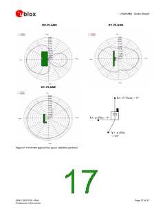
1.19.4 Embedded antenna operation
The embedded GNSS chip antenna provides optimal radiation efficiency 80% typ. with 80x40 mm
ground plane. The GNSS chip antenna provides linear polarization with peak gain 1.1 dBi and
radiation pattern optimized for portable devices. The chip antenna is insensitive to surroundings and
has high tolerance against frequency shifts. Figure 2 shows the typical free space radiation patterns
of the embedded GNSS chip antenna at 1575 GHz. However, on small ground plane widths, the
antenna gain and radiation efficiency is reduced.
UBX-15031574 - R04
Production Information
Page 16 of 31

 U-BLOX [ u-blox AG ]