Part Number 856929
140 MHz SAW Filter
Data Sheet
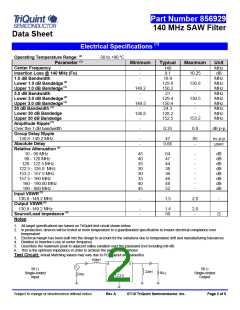
Electrical Specifications (1)
Operating Temperature Range: (2)
-30 to +80 oC
Parameter (3)
Minimum
Typical
140
9.1
19.9
129.9
150.2
21
129.4
150.4
24.3
Maximum
Unit
MHz
dB
Center Frequency
Insertion Loss @ 140 MHz (Fo)
1.0 dB Bandwidth
Lower 1.0 dB Bandedge (4)
Upper 1.0 dB Bandedge (4)
3.0 dB Bandwidth
Lower 3.0 dB Bandedge (4)
Upper 3.0 dB Bandedge (4)
30 dB Bandwidth (4)
Lower 30 dB Bandedge
Upper 30 dB Bandedge
Amplitude Ripple (5)
Over the 1 dB bandwidth
Group Delay Ripple
130.8 -149.2 MHz
-
-
-
-
-
10.25
-
MHz
MHz
MHz
MHz
MHz
MHz
MHz
MHz
MHz
130.8
149.2
-
-
-
-
130.5
149.5
-
-
-
-
126.8
-
128.2
152.5
153.2
-
0.35
0.8
dB p-p
-
-
47
0.66
85
-
ns p-p
µsec
Absolute Delay
Relative Attenuation (4)
10 - 90 MHz
45
40
35
30
30
35
40
45
64
47
44
38
36
46
48
52
-
-
-
-
-
-
-
-
dB
dB
dB
dB
dB
dB
dB
dB
90 - 120 MHz
120 - 122.5 MHz
122.5 - 126.8 MHz
153.2 - 157.5 MHz
157.5 - 160 MHz
160 - 190.00 MHz
190 - 800 MHz
Input VSWR (5)
130.8 -149.2 MHz
-
1.5
2.0
-
Output VSWR (5)
130.8 -149.2 MHz
-
-
1.4
50
2.0
-
-
Ω
Source/Load Impedance (6)
Notes:
1. All target specifications are based on TriQuint test circuit shown below
2. In production, devices will be tested at room temperature to a guardbanded specification to ensure electrical compliance over
temperature
3. Electrical margin has been built into the design to account for the variations due to temperature drift and manufacturing tolerances
4. Relative to Insertion Loss at center frequency
5. Describes the maximum peak to adjacent valley variation over the passband (not including roll-off)
6. This is the optimum impedance in order to achieve the performance shown
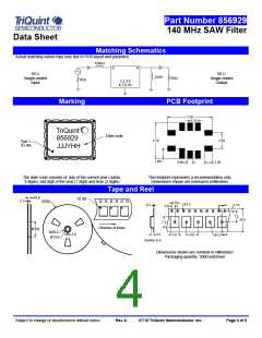
Test Circuit: Actual Matching values may vary due to PCB layout and parasitics
150nH
9
4
50
50
22nH
50
Single-ended
Input
Single-ended
Output
50
1,2,3,5
6,7,8,10
Subject to change or obsolescence without notice
Rev A
07/10 TriQuint Semiconductor, Inc.
Page 2 of 5

 TRIQUINT [ TRIQUINT SEMICONDUCTOR ]