TMC5130A DATASHEET (Rev. 1.14 / 2017-MAY-15)
11
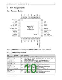
Pin
Number
Type Function
Left reference input (SPI_MODE=1, SD_MODE=0) or
REFL_STEP
8
DI
DI
STEP input when (SD_MODE=1 or SPI_MODE=0).
Right reference input (SPI_MODE=1, SD_MODE=0) or
DIR input (SD_MODE=1 or SPI_MODE=0).
REFR_DIR
VCC_IO
9
10
3.3V to 5V IO supply voltage for all digital pins.
Mode selection input with pullup resistor. When tied low, the
internal ramp generator generates step pulses. When tied high,
the STEP/DIR inputs control the driver. Integrated pullup resistor.
Mode selection input with pullup resistor. When tied low, the
chip is in standalone mode and pins have their CFG functions.
When tied high, the SPI or UART interfaces are available for
control. Integrated pullup resistor.
DI
(pu)
SD_MODE
11
DI
(pu)
SPI_MODE
12
GNDP
DNC.
OB1
13, 48
Power GND. Connect to GND plane near pin.
14, 16, 18,
20, 22, 41,
43, 45, 47
15
Do not connect these pins. Provided to increase creeping
distance on PCB in order to allow higher supply voltage without
coating.
Motor coil B output 1
Sense resistor connection for coil B. Place sense resistor to GND
near pin. An additional 100nF capacitor to GND (GND plane) is
recommended for best performance.
BRB
17
OB2
VS
19
Motor coil B output 2
Motor supply voltage. Provide filtering capacity near pin with
short loop to nearest GNDP pin (respectively via GND plane).
Encoder N-channel input (SD_MODE=0) or
21, 40
ENCN_DCO
23
24
DIO
DI
dcStep ready output (SD_MODE=1).
With SD_MODE=0, pull to GND or VCC_IO, if the pin is not used.
Encoder B-channel input (SD_MODE=0, SPI_MODE=1) or
dcStep enable input (SD_MODE=1, SPI_MODE=1) - tie to GND for
ENCB_DCEN_
CFG4
(tpu) normal operation (no dcStep).
Configuration input (SPI_MODE=0) (tristate detection)
Encoder A-channel input (SD_MODE=0, SPI_MODE=1) or
ENCA_DCIN_
CFG5
DI
(tpu) SPI_MODE=1) or
Configuration input (SPI_MODE=0) (tristate detection).
dcStep gating input for axis synchronization (SD_MODE=1,
25
26
Diagnostics output DIAG0.
Interrupt or STEP output for motion controller (SD_MODE=0,
SPI_MODE=1).
Use external pullup resistor with 47k or less in open drain mode.
Single wire I/O (negative) (only with SWSEL=1)
Diagnostics output DIAG1.
Position compare or DIR output for motion controller
(SD_MODE=0, SPI_MODE=1).
Use external pullup resistor with 47k or less in open drain mode.
Single wire I/O (positive) (only with SWSEL=1)
Single wire interface select input, tie high for use of single wire
interface (only when SPI_MODE=1). Integrated pull-down resistor.
Enable input or configuration / Enable input. The power stage
becomes switched off (all motor outputs floating) when this pin
becomes driven to a high level.
SWN_DIAG0
DIO
DIO
SWP_DIAG1
SWSEL
27
DI
(pd)
28
29
DRV_ENN_
CFG6
DI
(tpu)
Analog reference voltage for current scaling (optional mode) or
reference current for use of internal sense resistors
Analog GND. Tie to GND plane.
AIN_IREF
GNDA
30
32
AI
www.trinamic.com

 TRINAMIC [ TRINAMIC MOTION CONTROL GMBH & CO. KG. ]