TMC248-LA DATASHEET (Rev. 1.01 / 2013-MAR-26)
39
18 Table of Figures
Figure 1.1 TMC248 block diagram....................................................................................................................................4
Figure 2.1 TMC248 pin assignments................................................................................................................................6
Figure 3.1 stallGuard signal sensitivity curves.............................................................................................................8
Figure 3.2 Implementing stallGuard ...............................................................................................................................9
Figure 4.1 Relation between VIN and trip voltage of current sense comparator.............................................12
Figure 4.2 External DAC and PWM-DAC........................................................................................................................12
Figure 4.3 SPI Timing........................................................................................................................................................14
Figure 5.1 Analog control for standalone mode.......................................................................................................15
Figure 6.1 Schematic with RSH=RSA=RSB...........................................................................................................................17
Figure 7.1 Chopper phases ..............................................................................................................................................18
Figure 7.2 Chopper cycle ..................................................................................................................................................19
Figure 7.3 Voltage PWM generates motor current ...................................................................................................20
Figure 7.4 Controlling the driver with two PWMs in standalone mode............................................................22
Figure 7.5 Adapting sine wave for smooth motor operation...............................................................................22
Figure 8.1 RSLP versus IDH...................................................................................................................................................24
Figure 9.1 Overvoltage protection.................................................................................................................................26
Figure 11.1 Grounding TMC248.......................................................................................................................................30
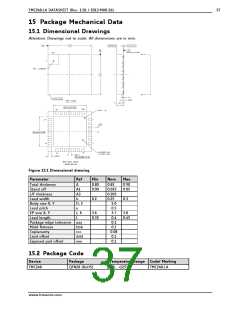
Figure 14.1 Dimensional drawing..................................................................................................................................37
www.trinamic.com

 TRINAMIC [ TRINAMIC MOTION CONTROL GMBH & CO. KG. ]