TSM9634
or
stage is protected against input overdrive by use of
an output current-limiting circuit of 3mA (typical) and
a 7V internal clamp protection circuit.
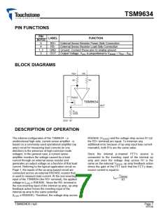
ꢀLOAꢁ x RSENSE
ꢀꢁS
ꢂ
R1
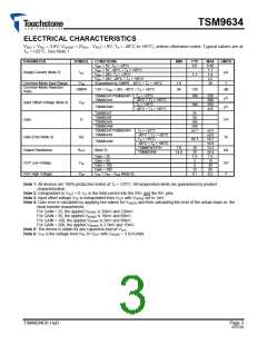
Table 1: Internal Gain Setting Resistors (Typical
Values)
Since the FET’s drain terminal is connected to
ROUT, the output voltage of the TSM9634 at the
OUT terminal is, therefore;
GAIN (V/V) R1 (Ω) ROUT (Ω) Part Number
ROUT
25
50
100
200
400
200
100
100
10k
10k
10k
20k
TSM9634T
TSM9634F
TSM9634H
TSM9634W
VOUT ꢂ ꢀLOAꢁ x RSENSE
x
R1
The current-sense amplifier’s gain accuracy is
therefore the ratio match of ROUT to R1. For each of
the four gain options available, Table 1 lists the
values for ROUT and R1. The TSM9634’s output
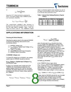
APPLICATIONS INFORMATION
and
Choosing the Sense Resistor
VOUT ꢀmaxꢁ
RSENSE
ꢂ
Selecting the optimal value for the external RSENSE
is based on the following criteria and for each
commentary follows:
GAꢀN ꢃ ꢀLOAꢁꢀmaxꢁ
where the full-scale VSENSE should be less than
VOUT(MAX)/GAIN at the application’s minimum RS+
terminal voltage. For best performance with a 3.6V
power supply, RSENSE should be chosen to
generate a VSENSE of: a) 120mV (for the 25V/V GAIN
option), b) 60mV (for the 50V/V GAIN option), c)
30mV (for the 100V/V GAIN option), or d) 15mV (for
the 200V/V GAIN option) at the full-scale ILOAD(MAX)
current in each application. For the case where the
minimum power supply voltage is higher than 3.6V,
each of the four full-scale VSENSEs above can be
increased.
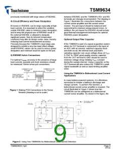
1) RSENSE Voltage Loss
2) VOUT Swing vs. Applied Input Voltage at VRS+
and Desired VSENSE
3) Total ILOAD Accuracy
4) Circuit Efficiency and Power Dissipation
5) RSENSE Kelvin Connections
1) RSENSE Voltage Loss
For lowest IR voltage loss in RSENSE, the smallest
usable value for RSENSE should be selected.
3) Total ILOAD Accuracy
2) VOUT Swing vs. Applied Input Voltage at VRS+
and Desired VSENSE
In the TSM9634’s linear region where
VOUT < VOUT(max), there are two specifications related
to the circuit’s accuracy: a) the TSM9634’s input
offset voltage (VOS = 250μV, max) and b) its gain
error (GE(max) = 0.5%). An expression for the
TSM9634’s total output voltage (+ error) is given by:
As there is no separate power supply pin for the
TSM9634, the circuit draws its power from the
applied voltage at both its RS+ and RS- terminals.
Therefore, the signal voltage at the OUT terminal is
bounded by the minimum supply voltage applied to
the TSM9634.
VOUT = [GAIN x (1 ± GE) x VSENSE] ± (GAIN x VOS)
Therefore,
A large value for RSENSE permits the use of smaller
load currents to be measured more accurately
because the effects of offset voltages are less
significant when compared to larger VSENSE voltages.
Due care though should be exercised as
VOUT(max) = VRS+(min) - VSENSE(max) – VOH(max)
Page 8
TSM9634DS r1p0
RTFDS

 TOUCHSTONE [ TOUCHSTONE SEMICONDUCTOR INC ]