TPC8018-H
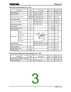
Electrical Characteristics (Ta = 25°C)
Characteristic
Gate leakage current
Symbol
Test Condition
= ±16 V, V = 0 V
Min
Typ.
Max
Unit
I
V
V
⎯
⎯
30
15
1.1
⎯
⎯
25
⎯
⎯
⎯
⎯
⎯
±10
10
⎯
µA
µA
GSS
GS
DS
DS
Drain cutoff current
I
= 30 V, V
= 0 V
DSS
GS
GS
GS
V
V
I
I
= 10 mA, V
= 10 mA, V
= 0 V
⎯
(BR) DSS
(BR) DSX
D
D
Drain-source breakdown voltage
Gate threshold voltage
V
V
= −20 V
⎯
⎯
V
V
V
V
V
= 10 V, I = 1 mA
⎯
2.3
6.2
4.6
⎯
th
DS
GS
GS
DS
D
= 4.5 V, I = 9 A
4.8
3.5
50
D
Drain-source ON-resistance
R
mΩ
S
DS (ON)
= 10 V, I = 9 A
D
Forward transfer admittance
Input capacitance
|Y |
fs
= 10 V, I = 9 A
D
C
C
2265
255
1045
⎯
iss
V
= 10 V, V
= 0 V, f = 1 MHz
pF
Reverse transfer capacitance
Output capacitance
⎯
DS
GS
rss
C
oss
⎯
Rise time
t
⎯
⎯
⎯
⎯
5
⎯
⎯
⎯
⎯
r
I
= 9 A
D
10 V
V
GS
V
OUT
0 V
Turn-on time
Switching time
t
14
11
50
on
ns
Fall time
t
f
∼
V
15 V
DD
Turn-off time
t
off
<
Duty 1%, t = 10 µs
w
∼
V
V
24 V, V
= 10 V, I = 18 A
⎯
⎯
⎯
⎯
⎯
38
21
7.3
9
⎯
⎯
⎯
⎯
⎯
DD
DD
GS
GS
D
Total gate charge
(gate-source plus gate-drain)
Q
g
∼
24 V, V
= 5 V, I = 18 A
D
nC
Gate-source charge 1
Gate-drain (“Miller”) charge
Gate switch charge
Q
Q
gs1
∼
V
24 V, V
= 10 V, I = 18 A
Q
DD
GS
D
gd
12
SW
Source-Drain Ratings and Characteristics (Ta = 25°C)
Characteristic
Symbol
Test Condition
Min
Typ.
Max
Unit
Drain reverse current
Forward voltage (diode)
Pulse (Note 1)
I
⎯
⎯
⎯
⎯
⎯
72
A
V
DRP
V
I
= 18 A, V = 0 V
GS
−1.2
DSF
DR
3
2006-11-16

 TOSHIBA [ TOSHIBA ]