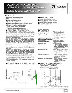
XC6101~XC6107, XC6111~XC6117 Series
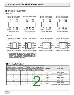
■PIN CONFIGURATION
●SOT-25
XC6101, XC6102 Series
XC6111, XC6112 Series
XC6103 & XC6113 Series
XC6104, XC6105 Series
XC6114, XC6115 Series
XC6106, XC6107 Series
XC6116, XC6117 Series
MRB
V
IN
WD
WD
V
IN
V
IN
WD
4
V
IN
4
5
4
4
5
5
5
1
2
3
1
2
3
MRB
1
2
3
1
2
3
MRB
RESETB
V
SS RESET
RESET
V
SS
RESETB
V
SS RESET
RESETB
V
SS
SOT-25 (TOP VIEW)
SOT-25 (TOP VIEW)
SOT-25 (TOP VIEW)
SOT-25 (TOP VIEW)
●USP-6C
XC6101, XC6102 Series
XC6111, XC6112 Series
XC6103 & XC6113 Series
XC6104, XC6105 Series
XC6114, XC6115 Series
XC6106, XC6107 Series
XC6116, XC6117 Series
USP-6C (BOTTOM VIEW)
USP-6C (BOTTOM VIEW)
USP-6C (BOTTOM VIEW)
USP-6C (BOTTOM VIEW)
* The dissipation pad for the USP-6C package should be
solder-plated in recommended mount pattern and metal
masking so as to enhance mounting strength and heat
release. If the pad needs to be connected to other pins, it
should be connected to the VSS pin.
■PIN ASSIGNMENT
PIN NUMBER
XC6101, XC6102
XC6111, XC6112
XC6103
XC6104, XC6105 XC6106, XC6107
XC6114, XC6115 XC6116, XC6117
PIN NAME
FUNCTION
XC6113
SOT-25 USP-6C SOT-25 USP-6C SOT-25 USP-6C SOT-25 USP-6C
Reset Output
(VDFL: Low Level When Detected)
Ground
RESETB
VSS
1
4
-
-
1
4
1
4
2
3
4
5
5
2
1
6
2
3
4
5
5
2
1
6
2
-
5
-
2
4
-
5
1
-
MRB
WD
VIN
Manual Reset
Watchdog
4
5
1
6
5
6
Power Input
Reset Output
(VDFH: High Level When Detected)
-
-
1
4
3
2
3
2
RESET
2/26

 TOREX [ Torex Semiconductor ]