TK111xxM
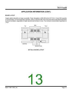
APPLICATION INFORMATION
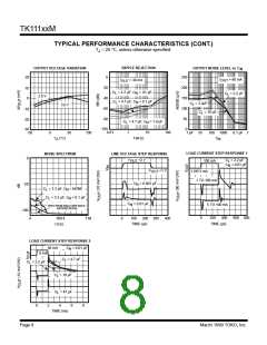
INPUT-OUTPUT CAPACITORS
Linearregulatorsrequireanoutputcapacitorinordertomaintainregulatorloopstability.Thiscapacitorshouldbeselected
to ensure stable operation over the desired temperature and load range. The graphs below show the effects of
capacitance value and Equivalent Series Resistance (ESR) on the stable operation area.
111xx
C
L
ESR
C = 1 µF
C = 2.2 µF
C = 3.3 µF
C = 10 µF
L
L
L
L
1000
100
1000
100
1000
100
1000
100
10
10
10
10
STABLE
OPERATION
AREA
STABLE
OPERATION
AREA
STABLE
OPERATION
AREA
STABLE
OPERATION
AREA
1
1
1
1
0.1
0.1
0.1
0.1
0 .01
0 .01
0 .01
0 .01
130
130
130
130
1
50
I
100
1
50
I
100
1
50
I
100
1
50
I
100
(mA)
(mA)
OUT
(mA)
(mA)
OUT
OUT
OUT
In general, the capacitor should be at least 1 µF (aluminum electrolytic) and be rated for the actual ambient operating
temperature range. The table below shows typical characteristics for several types and values of capacitance. Please
note that the ESR varies widely depending upon manufacturer, type, size, and material.
ESR
Capacitance
Aluminum
Capacitor
Tantalum
Capacitor
Ceramic
Capacitor
1.0 µF
2.2 µF
3.3 µF
10 µF
2.4 Ω
2.0 Ω
4.6 Ω
1.4 Ω
2.3 Ω
1.9 Ω
1.0 Ω
0.5 Ω
0.140 Ω
0.059 Ω
0.049 Ω
0.025 Ω
Note: ESR is measured at 10 kHz.
Page 12
March 1999 TOKO, Inc.

 TOKO [ TOKO, INC ]