SN65HVD230
SN65HVD231
SN65HVD232
www.ti.com
SLOS346H–MARCH 2001–REVISED JULY 2006
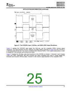
APPLICATION INFORMATION (continued)
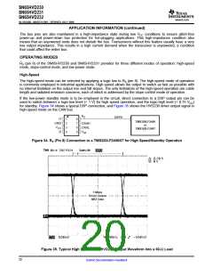
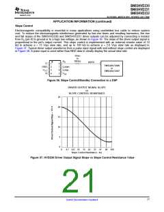
Slope Control
Electromagnetic compatibility is essential in many applications using unshielded bus cable to reduce system
cost. To reduce the electromagnetic interference generated by fast rise times and resulting harmonics, the rise
and fall slopes of the SN65HVD230 and SN65HVD231 driver outputs can be adjusted by connecting a resistor
from RS (pin 8) to ground or to a logic low voltage, as shown in Figure 36. The slope of the driver output signal is
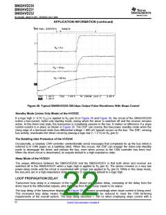
proportional to the pin's output current. This slope control is implemented with an external resistor value of 10
kΩ to achieve a ≈ 15 V/µs slew rate, and up to 100 kΩ to achieve a ≈ 2.0 V/µs slew rate as displayed in
Figure 37. Typical driver output waveforms from a pulse input signal with and without slope control are displayed
in Figure 38. A pulse input is used rather than NRZ data to clearly display the actual slew rate.
10 kΩ
to
100 kΩ
R
S
IOPF6
D
1
2
3
4
8
7
6
5
TMS320LF2406
or
TMS320LF2407
GND
CANH
CANL
V
CC
R
V
ref
Figure 36. Slope Control/Standby Connection to a DSP
DRIVER OUTPUT SIGNAL SLOPE
vs
SLOPE CONTROL RESISTANCE
25
20
15
10
5
0
0
0
10 20
30 40
50 60
33
70 80 90
47 68 100
4.7 6.8 10
15 22
Slope Control Resistance – kΩ
Figure 37. HVD230 Driver Output Signal Slope vs Slope Control Resistance Value
21
Submit Documentation Feedback

 TI [ TEXAS INSTRUMENTS ]