SN65HVD230
SN65HVD231
SN65HVD232
www.ti.com
SLOS346H–MARCH 2001–REVISED JULY 2006
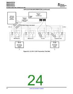
APPLICATION INFORMATION (continued)
The bus pins are also maintained in a high-impedance state during low VCC conditions to ensure glitch-free
power-up and power-down bus protection for hot-plugging applications. This high-impedance condition also
means that an unpowered node does not disturb the bus. Transceivers without this feature usually have a very
low output impedance. This results in a high current demand when the transceiver is unpowered, a condition
that could affect the entire bus.
OPERATING MODES
RS (pin 8) of the SN65HVD230 and SN65HVD231 provides for three different modes of operation: high-speed
mode, slope-control mode, and low-power mode.
High-Speed
The high-speed mode can be selected by applying a logic low to RS (pin 8). The high-speed mode of operation
is commonly employed in industrial applications. High-speed allows the output to switch as fast as possible with
no internal limitation on the output rise and fall slopes. The only limitations of the high-speed operation are cable
length and radiated emission concerns, each of which is addressed by the slope control mode of operation.
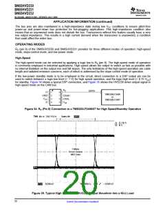
If the low-power standby mode is to be employed in the circuit, direct connection to a DSP output pin can be
used to switch between a logic-low level (< 1 V) for high speed operation, and the logic-high level (> 0.75 VCC
)
for standby. Figure 34 shows a typical DSP connection, and Figure 35 shows the HVD230 driver output signal in
high-speed mode on the CAN bus.
R
S
IOPF6
D
1
2
3
4
8
7
6
5
TMS320LF2406
or
TMS320LF2407
GND
CANH
CANL
V
CC
R
V
ref
Figure 34. RS (Pin 8) Connection to a TMS320LF2406/07 for High Speed/Standby Operation
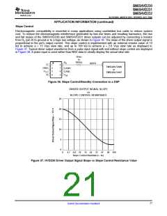
1 Mbps
Driver Output
NRZ Data
1
Figure 35. Typical High Speed SN65HVD230 Output Waveform Into a 60-Ω Load
20
Submit Documentation Feedback

 TI [ TEXAS INSTRUMENTS ]