SN65HVD230
SN65HVD231
SN65HVD232
www.ti.com
SLOS346H–MARCH 2001–REVISED JULY 2006
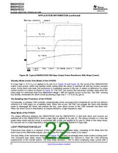
APPLICATION INFORMATION
This application provides information concerning the implementation of the physical medium attachment layer in
a CAN network according to the ISO 11898 standard. It presents a typical application circuit and test results, as
well as discussions on slope control, total loop delay, and interoperability in 5-V systems.
INTRODUCTION
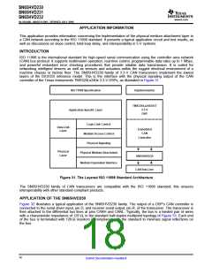
ISO 11898 is the international standard for high-speed serial communication using the controller area network
(CAN) bus protocol. It supports multimaster operation, real-time control, programmable data rates up to 1 Mbps,
and powerful redundant error checking procedures that provide reliable data transmission. It is suited for
networking intelligent devices as well as sensors and actuators within the rugged electrical environment of a
machine chassis or factory floor. The SN65HVD230 family of 3.3-V CAN transceivers implement the lowest
layers of the ISO/OSI reference model. This is the interface with the physical signaling output of the CAN
controller of the Texas Instruments TMS320Lx240x 3.3-V DSPs, as illustrated in Figure 31.
Implementation
ISO 11898 Specification
TMS320Lx2403/6/7
3.3-V
DSP
Application Specific Layer
Logic Link Control
Medium Access Control
Physical Signaling
Data-Link
Layer
Embedded
CAN
Controller
Physical
Layer
Physical Medium Attachment
SN65HVD230
CAN Bus-Line
Medium Dependent Interface
Figure 31. The Layered ISO 11898 Standard Architecture
The SN65HVD230 family of CAN transceivers are compatible with the ISO 11898 standard; this ensures
interoperability with other standard-compliant products.
APPLICATION OF THE SN65HVD230
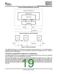
Figure 32 illustrates a typical application of the SN65HVD230 family. The output of a DSP's CAN controller is
connected to the serial driver input, pin D, and receiver serial output, pin R, of the transceiver. The transceiver is
then attached to the differential bus lines at pins CANH and CANL. Typically, the bus is a twisted pair of wires
with a characteristic impedance of 120 Ω, in the standard half-duplex multipoint topology of Figure 33. Each end
of the bus is terminated with 120-Ω resistors in compliance with the standard to minimize signal reflections on
the bus.
18
Submit Documentation Feedback

 TI [ TEXAS INSTRUMENTS ]