ULN2002A, ULN2003A, ULN2003AI, ULN2004A
ULQ2003A, ULQ2004A
www.ti.com
SLRS027J –DECEMBER 1976–REVISED JUNE 2010
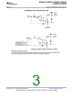
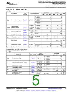
SCHEMATICS (EACH DARLINGTON PAIR)
10.5 kW
7.2 kW
3 kW
ULN2002A
R
B
ULN/ULQ2003A: R = 2.7 kW
B
ULN2003AI: R = 2.7 kW
7.2 kW
3 kW
B
ULN/ULQ2004A: R = 10.5 kW
B
ULN2003A, ULN2003AI, ULN2004A, ULQ2003A, ULQ2004A
All resistor values shown are nominal.
The collector-emitter diode is a parasitic structure and should not be used to conduct current. If the collector(s) go
below ground an external Schottky diode should be added to clamp negative undershoots.
Copyright © 1976–2010, Texas Instruments Incorporated
Submit Documentation Feedback
3
Product Folder Link(s): ULN2002A ULN2003A ULN2003AI ULN2004A ULQ2003A ULQ2004A

 TI [ TEXAS INSTRUMENTS ]