UC2906
UC3906
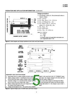
the charger a low current turn on mode. The output cur-
rent of the charger is limited to a low-level until the battery
reaches a specified voltage, preventing a high current
charging if a battery cell is shorted. Figure 2 shows the
state diagram of the charger. Upon turn on the UV sense
circuitry puts the charger in state 1, the high rate bulk-
charge state. In this state, once the enable threshold has
been exceeded, the charger will supply a peak current
that is determined by the 250mV offset in the C/L ampli-
fier and the sensing resistor RS.
Internal Reference Temperature Characteristic and
Tolerance
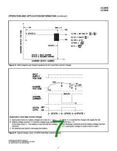
To guarantee full re-charge of the battery, the charger’s
voltage loop has an elevated regulating level, VOC, during
state 1 and state 2. When the battery voltage reaches
95% of VOC, the charger enters the over-charge state,
state 2. The charger stays in this state until the OVER-
CHARGE TERMINATE pin goes high. In Figure 1, the
charger uses the current sense amplifier to generate this
signal by sensing when the charge current has tapered to
a specified level, IOCT. Alternatively the over-charge could
have been controlled by an external source, such as a
timer, by using the OVER-CHARGE INDICATE signal at
Pin 9. If a load is applied to the battery and begins to dis-
charge it, the charger will contribute its full output to the
load. If the battery drops 10% below the float level, the
charger will reset itself to state 1. When the load is re-
moved a full charge cycle will follow. A graphical repre-
sentation of a charge, and discharge, cycle of the dual
lever float charger is shown in Figure 3.
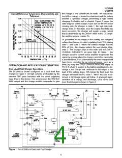
OPERATION AND APPLICATION INFORMATION
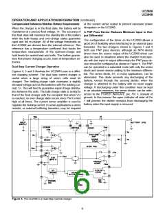
Dual Level Float Charger Operations
The UC2906 is shown configured as a dual level float
charger in Figure 1. All high currents are handled by the
external PNP pass transistor with the driver supplying
base drive to this device. This scheme uses the TRICKLE
BIAS output and the charge enable comparator to give
Figure 1. The UC2906 in a Dual Level Float Charger
4

 TI [ TEXAS INSTRUMENTS ]