www.ti.com
ꢀꢁ ꢂ ꢃꢄ ꢅꢆ ꢇ
SLVS398D − JUNE 2001 − REVISED JULY 2003
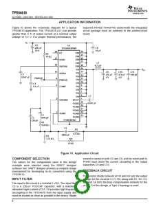
Figure 21 shows the schematic diagram for a reduced
size, high frequency application using the TPS54610. The
TPS54610 (U1) can provide up to 6 A of output current at
a nominal output voltage of 1.8 V. A small size 0.56 uH
inductor is used and the switching frequency is set to 680
kHz by R1. The compensation network is optimized for fast
transient response as shown in Figure 21. For good
thermal performance, the PowerPAD underneath the
integrated circuit TPS54610 needs to be soldered well to
the printed-circuit board. Application information is
available in TI literature number SLVA107, Designing for
Small-Size, High-Frequency Applications With Swift
Family of Synchronous Buck Regulators.
V
I
U1
C1
10 µF
C2
10 µF
TPS54610PWP
R1
28
24
23
22
21
RT
VIN
71.5 kΩ
VIN
VIN
VIN
VIN
PH
PH
PH
PH
PH
PH
PH
PH
27
26
SYNC
SS/ENA
C3
20
14
13
0.047 µF
C4
25
VBIAS
PWRGD
COMP
1 µF
12
11
4
3
10
9
C5
R2
8
7
6
10 kΩ
L1
0.56 µH
470 pF
C6
V
O
PH
BOOT
PGND
PGND
470 pF
2
1
5
C7
C8
150 µF
C9
150 µF
C10
1 pF
+
+
VSENSE
19
18
17
16
15
0.047 µF
R5
1.47 kΩ
R4
2.4 Ω
PGND
PGND
PGND
R3
AGND
39 Ω
C11
3300 pF
R6
1.5 kΩ
POWERPAD
C12
0.012 µF
Figure 21. Small Size, High Frequency Design
TRANSIENT RESPONSE, 1.5-A to 4.5-A STEP
10 µs/div
Figure 22
11

 TI [ TEXAS INSTRUMENTS ]