TPS54360
www.ti.com
SLVSBB4C –AUGUST 2012–REVISED OCTOBER 2012
Power Dissipation Estimate
The following formulas show how to estimate the TPS54360 power dissipation under continuous conduction
mode (CCM) operation. These equations should not be used if the device is operating in discontinuous
conduction mode (DCM).
The power dissipation of the IC includes conduction loss (PCOND), switching loss (PSW), gate drive loss (PGD) and
supply current (PQ). Example calculations are shown with the 12 V typical input voltage of the design example.
æ
ç
è
ö
÷
ø
V
5 V
2
2
OUT
P
=
I
´ R
´
= 3.5 A ´ 92 mW ´
= 0.47 W
(
)
COND
OUT
DS on
( )
V
12 V
IN
(49)
(50)
(51)
(52)
spacer
P
= V ´ f
´I
´ t
= 12 V ´ 600 kHz ´ 3.5 A ´ 4.9 ns = 0.123 W
rise
SW
IN
SW
OUT
spacer
P
= V ´ Q ´ f
= 12 V ´ 3nC´ 600 kHz = 0.022 W
SW
GD
IN
G
spacer
P
= V ´ I = 12 V ´ 146 mA = 0.0018 W
IN Q
Q
Where:
IOUT is the output current (A).
RDS(on) is the on-resistance of the high-side MOSFET (Ω).
VOUT is the output voltage (V).
VIN is the input voltage (V).
fsw is the switching frequency (Hz).
trise is the SW pin voltage rise time and can be estimated by trise = VIN x 0.16ns/V + 3.0ns
QG is the total gate charge of the internal MOSFET
IQ is the operating nonswitching supply current
Therefore,
P
= P
+ P
+ P + P = 0.47 W + 0.123 W + 0.022 W + 0.0018 W = 0.616 W
TOT
COND
SW GD Q
(53)
(54)
For given TA,
T = T + R ´P
TOT
J
A
TH
For given TJMAX = 150°C
TA max = TJ max - RTH ´PTOT
(
)
(
)
(55)
Where:
Ptot is the total device power dissipation (W).
TA is the ambient temperature (°C).
TJ is the junction temperature (°C).
RTH is the thermal resistance of the package (°C/W).
TJMAX is maximum junction temperature (°C).
TAMAX is maximum ambient temperature (°C).
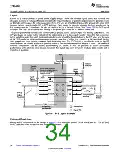
There will be additional power losses in the regulator circuit due to the inductor ac and dc losses, the catch diode
and PCB trace resistance impacting the overall efficiency of the regulator.
Copyright © 2012, Texas Instruments Incorporated
Submit Documentation Feedback
33
Product Folder Links: TPS54360

 TI [ TEXAS INSTRUMENTS ]