TPS2041B-Q1
TPS2042B-Q1
TPS2051B-Q1
SLVS782A –NOVEMBER 2007–REVISED JUNE 2010
www.ti.com
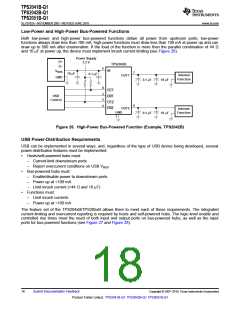
Low-Power and High-Power Bus-Powered Functions
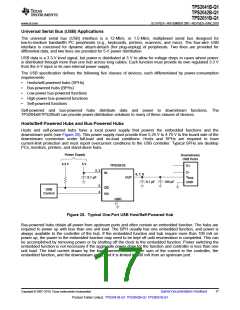
Both low-power and high-power bus-powered functions obtain all power from upstream ports; low-power
functions always draw less than 100 mA; high-power functions must draw less than 100 mA at power up and can
draw up to 500 mA after enumeration. If the load of the function is more than the parallel combination of 44 Ω
and 10 mF at power up, the device must implement inrush current limiting (see Figure 26).
Power Supply
D+
D−
3.3 V
TPS2042B
2
8
IN
V
BUS
7
10 µF
0.1 µF
Internal
Function
OUT1
GND
0.1 µF
10 µF
OC1
EN1
OC2
EN2
3
5
USB
Control
6
4
OUT2
GND
Internal
Function
0.1 µF
10 µF
1
Figure 26. High-Power Bus-Powered Function (Example, TPS2042B)
USB Power-Distribution Requirements
USB can be implemented in several ways, and, regardless of the type of USB device being developed, several
power-distribution features must be implemented.
•
•
Hosts/self-powered hubs must:
–
–
Current-limit downstream ports
Report overcurrent conditions on USB VBUS
Bus-powered hubs must:
–
–
–
Enable/disable power to downstream ports
Power up at <100 mA
Limit inrush current (<44 Ω and 10 mF)
•
Functions must:
–
–
Limit inrush currents
Power up at <100 mA
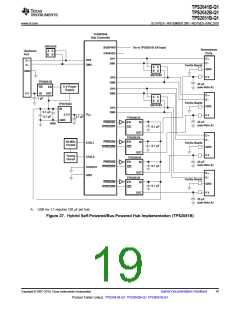
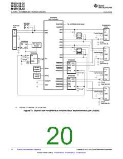
The feature set of the TPS204xB/TPS205xB allows them to meet each of these requirements. The integrated
current-limiting and overcurrent reporting is required by hosts and self-powered hubs. The logic-level enable and
controlled rise times meet the need of both input and output ports on bus-powered hubs, as well as the input
ports for bus-powered functions (see Figure 27 and Figure 28).
18
Submit Documentation Feedback
Copyright © 2007–2010, Texas Instruments Incorporated
Product Folder Link(s): TPS2041B-Q1 TPS2042B-Q1 TPS2051B-Q1

 TI [ TEXAS INSTRUMENTS ]