TPA3116D2
TPA3118D2
TPA3130D2
SLOS708B –APRIL 2012–REVISED MAY 2012
www.ti.com
10 µH
L1
OUTP
C2
0.68 µF
4 W - 8 W
10 µH
L2
OUTN
C3
0.68 µF
Ferrite
Chip Bead
OUTP
OUTN
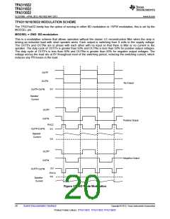
1 nF
1 nF
4 W - 8 W
Ferrite
Chip Bead
Figure 34.
AM AVOIDANCE EMI REDUCTION
To reduce interference in the AM radio band, the TPA3116D2 has the ability to change the switching frequency
via AM<2:0> pins. The recommended frequencies are listed in Table 6. The fundamental frequency and its
second harmonic straddle the AM radio band listed. This eliminates the tones that can be present due to the
switching frequency being demodulated by the AM radio.
Table 6. AM Frequencies
US
EUROPEAN
AM FREQUENCY (kHz)
522-540
AM FREQUENCY (kHz)
SWITCHING FREQUENCY (kHz)
AM2
AM1
AM0
540-917
917-1125
1125-1375
1375-1547
540-914
500
0
0
0
0
0
0
0
0
0
1
0
0
1
0
1
0
1
0
0
1
0
0
0
1
914-1122
1122-1373
1373-1548
600 (or 400)
500
600 (or 400)
1547-1700
1548-1701
600 (or 500)
PRINTED-CIRCUIT BOARD (PCB LAYOUT)
The TPA3116D2 can be used with a small, inexpensive ferrite bead output filter for most applications. However,
since the class-D switching edges are fast, it is necessary to take care when planning the layout of the printed
circuit board. The following suggestions will help to meet EMC requirements.
•
Decoupling capacitors — The high-frequency decoupling capacitors should be placed as close to the PVCC
and AVCC terminals as possible. Large (100 μF or greater) bulk power supply decoupling capacitors should
be placed near the TPA3116D2 on the PVCC supplies. Local, high-frequency bypass capacitors should be
placed as close to the PVCC pins as possible. These caps can be connected to the IC GND pad directly for
an excellent ground connection. Consider adding a small, good quality low ESR ceramic capacitor between
220 pF and 1 nF and a larger mid-frequency cap of value between 100 nF and 1 µF also of good quality to
the PVCC connections at each end of the chip.
•
•
Keep the current loop from each of the outputs through the ferrite bead and the small filter cap and back to
GND as small and tight as possible. The size of this current loop determines its effectiveness as an antenna.
Grounding — The PVCC decoupling capacitors should connect to GND. All ground should be connected at
the IC GND, which should be used as a central ground connection or star ground for the TPA3116D2.
24
Submit Documentation Feedback
Copyright © 2012, Texas Instruments Incorporated
Product Folder Link(s): TPA3116D2 TPA3118D2 TPA3130D2

 TI [ TEXAS INSTRUMENTS ]