TPA3116D2
TPA3118D2
TPA3130D2
www.ti.com
SLOS708B –APRIL 2012–REVISED MAY 2012
•
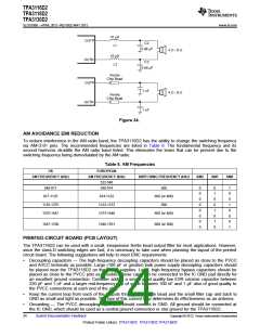
Output filter — The ferrite EMI filter (see Figure 34) should be placed as close to the output terminals as
possible for the best EMI performance. The LC filter should be placed close to the outputs. The capacitors
used in both the ferrite and LC filters should be grounded.
For an example layout, see the TPA3116D2 Evaluation Module (TPA3116D2EVM) User Manual. Both the EVM
user manual and the thermal pad application report are available on the TI Web site at http://www.ti.com.
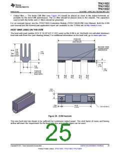
HEAT SINK USED ON THE EVM
The heat sink (part number ATS-TI 10 OP-521-C1-R1) used on the EVM is an 14x25x50 mm extruded aluminum
heat sink with three fins (see drawing below). For additional information on the heat sink, go to www.qats.com.
50.00 0.38
[1.969 .015]
SINK LENGTH
MACHINE THESE
3 EDGES AFTER
0.00
ANODIZATION
25.00
–0.60
3.00
[.118]
+.000
–.024
SINK HEIGHT
.984
1.00
[.118]
6.35
[.250]
3.00
[.118]
13.90 0.38
[.547 .015]
BASE WIDTH
6.95
[.274]
5.00
[.197]
40.00
[1.575]
2X 4-40 x 6.5
Figure 35. EVM Heatsink
This size heat sink has shown to be sufficient for continuous output power. The crest factor of music and having
airflow will lower the requirement for the heat sink size and smaller types can be used.
Copyright © 2012, Texas Instruments Incorporated
Submit Documentation Feedback
25
Product Folder Link(s): TPA3116D2 TPA3118D2 TPA3130D2

 TI [ TEXAS INSTRUMENTS ]