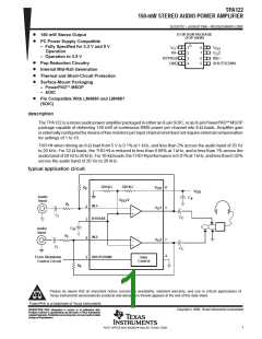
TPA122
150-mW STEREO AUDIO POWER AMPLIFIER
SLOS211C – AUGUST1998 – REVISED MARCH 2000
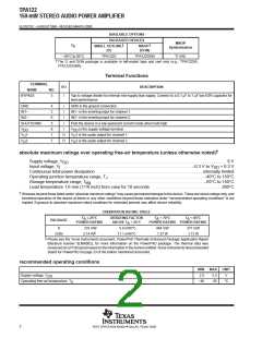
AVAILABLE OPTIONS
PACKAGED DEVICES
†
MSOP
Symbolization
†
MSOP
T
A
SMALL OUTLINE
(D)
(DGN)
–40°C to 85°C
TPA122D
TPA122DGN
TI AAE
†
The D and DGN package is available in left-ended tape and reel only (e.g., TPA122DR,
TPA122DGNR).
Terminal Functions
TERMINAL
NAME
BYPASS
I/O
DESCRIPTION
NO.
3
I
Tap to voltage divider for internal mid-supply bias supply. Connect to a 0.1 µF to 1 µF low ESR capacitor for
best performance.
GND
4
2
6
5
8
1
7
I
I
GND is the ground connection.
IN1–
IN1– is the inverting input for channel 1.
IN2– is the inverting input for channel 2.
Puts the device in a low quiescent current mode when held high
IN2–
I
SHUTDOWN
I
V
V
V
I
V
V
V
is the supply voltage terminal.
DD
DD
1
2
O
O
1 is the audio output for channel 1.
2 is the audio output for channel 2.
O
O
O
O
†
absolute maximum ratings over operating free-air temperature (unless otherwise noted)
Supply voltage, V
. . . . . . . . . . . . . . . . . . . . . . . . . . . . . . . . . . . . . . . . . . . . . . . . . . . . . . . . . . . . . . . . . . . . . . . . 6 V
DD
Input voltage, V . . . . . . . . . . . . . . . . . . . . . . . . . . . . . . . . . . . . . . . . . . . . . . . . . . . . . . . . . . . . –0.3 V to V + 0.3 V
I
DD
Continuous total power dissipation . . . . . . . . . . . . . . . . . . . . . . . . . . . . . . . . . . . . . . . . . . . . . . . . . internally limited
Operating junction temperature range, T . . . . . . . . . . . . . . . . . . . . . . . . . . . . . . . . . . . . . . . . . . . –40°C to 150°C
J
Storage temperature range, T
. . . . . . . . . . . . . . . . . . . . . . . . . . . . . . . . . . . . . . . . . . . . . . . . . . . –65°C to 150°C
stg
Lead temperature 1,6 mm (1/16 inch) from case for 10 seconds . . . . . . . . . . . . . . . . . . . . . . . . . . . . . . . 260°C
†
Stresses beyond those listed under “absolute maximum ratings” may cause permanent damage to the device. These are stress ratings only, and
functional operation of the device at these or any other conditions beyond those indicated under “recommended operating conditions” is not
implied. Exposure to absolute-maximum-rated conditions for extended periods may affect device reliability.
DISSIPATION RATING TABLE
T
≤ 25°C
DERATING FACTOR
T
= 70°C
T = 85°C
A
A
A
PACKAGE
POWER RATING
ABOVE T = 25°C
POWER RATING POWER RATING
A
D
725 mW
5.8 mW/°C
464 mW
1.37 W
377 mW
1.11 W
‡
DGN
2.14 W
17.1 mW/°C
‡
Please see the Texas Instruments document, PowerPAD Thermally Enhanced Package Application Report
(literature number SLMA002), for more information on the PowerPAD package. The thermal data was
measured on a PCB layout based on the information in the section entitled Texas InstrumentsRecommended
Board for PowerPAD on page 33 of the before mentioned document.
recommended operating conditions
MIN
2.5
MAX
5.5
UNIT
V
Supply voltage, V
DD
Operating free-air temperature, T
–40
85
°C
A
2
POST OFFICE BOX 655303 • DALLAS, TEXAS 75265

 TI [ TEXAS INSTRUMENTS ]