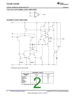
TL072-EP, TL074-EP
SLOS747C –OCTOBER 2011–REVISED AUGUST 2012
www.ti.com
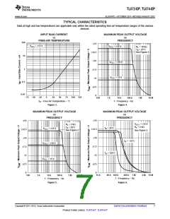
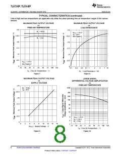
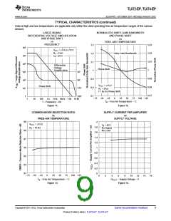
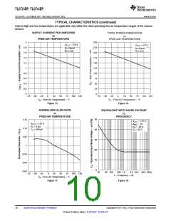
TYPICAL CHARACTERISTICS
Table of Graphs
FIGURE
3
IIB
Input bias current
vs Free-air temperature
vs Frequency
4, 5, 6
7
vs Free-air temperature
vs Load resistance
vs Supply voltage
VOM
Maximum peak output voltage
8
9
vs Free-air temperature
10
11
11
12
12
13
14
15
16
17
18
19
20
21
AVD
Large-signal differential voltage amplification
vs Frequency
Phase shift
vs Frequency
Normalized unity-gain bandwidth
Phase shift
vs Free-air temperature
vs Free-air temperature
vs Free-air temperature
vs Supply voltage
vs Free-air temperature
vs Free-air temperature
vs Free-air temperature
vs Frequency
CMRR
ICC
PD
Common-mode rejection ratio
Supply current per amplifier
Total power dissipation
Normalized slew rate
Vn
Equivalent input noise voltage
Total harmonic distortion
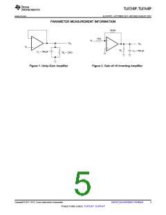
Voltage-follower large-signal pulse response
Output voltage
THD
vs Frequency
vs Time
VO
vs Elapsed time
6
Submit Documentation Feedback
Copyright © 2011–2012, Texas Instruments Incorporated
Product Folder Link(s): TL072-EP TL074-EP

 TI [ TEXAS INSTRUMENTS ]