TAS5711
www.ti.com
SLOS600 –DECEMBER 2009
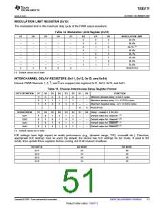
MODULATION LIMIT REGISTER (0x10)
The modulation limit is the maximum duty cycle of the PWM output waveform.
Table 14. Modulation Limit Register (0x10)
D7
–
D6
–
D5
–
D4
–
D3
–
D2
0
D1
0
D0
0
MODULATION LIMIT
99.2%
–
–
–
–
–
0
0
1
98.4%
(1)
–
–
–
–
–
0
1
0
97.7%
–
–
–
–
–
0
1
1
96.9%
96.1%
–
–
–
–
–
1
0
0
–
–
–
–
–
1
0
1
95.3%
–
–
–
–
–
1
1
0
94.5%
–
–
–
–
–
1
1
1
93.8%
0
0
0
0
0
–
–
–
RESERVED
(1) Default values are in bold.
INTERCHANNEL DELAY REGISTERS (0x11, 0x12, 0x13, and 0x14)
Internal PWM Channels 1, 2, 1, and 2 are mapped into registers 0x11, 0x12, 0x13, and 0x14.
Table 15. Channel Interchannel Delay Register Format
BITS DEFINITION
D7
0
D6
0
D5
0
D4
0
D3
0
D2
0
D1
–
D0
–
FUNCTION
Minimum absolute delay, 0 DCLK cycles
Maximum positive delay, 31 × 4 DCLK cycles
Maximum negative delay, –32 × 4 DCLK cycles
RESERVED
0
1
1
1
1
1
–
–
1
0
0
0
0
0
–
–
0
0
SUBADDRESS
0x11
D7
1
D6
0
D5
1
D4
0
D3
1
D2
1
D1
–
D0 Delay = (value) × 4 DCLKs
(1)
(1)
(1)
(1)
–
–
–
–
Default value for channel 1
Default value for channel 2
Default value for channel 1
Default value for channel 2
0x12
0
1
0
1
0
1
–
0x13
1
0
1
0
1
1
–
0x14
0
1
0
1
0
1
–
(1) Default values are in bold.
ICD settings have high impact on audio performance (e.g., dynamic range, THD, crosstalk etc.). Therefore,
appropriate ICD settings must be used. By default, the device has ICD settings for AD mode. If used in BD
mode, then update these registers before coming out of all-channel shutdown.
REGISTER
0x11
AD MODE
BD MODE
AC
54
B8
60
A0
48
0x12
0x13
AC
54
0x14
Copyright © 2009, Texas Instruments Incorporated
Submit Documentation Feedback
51
Product Folder Link(s): TAS5711

 TI [ TEXAS INSTRUMENTS ]