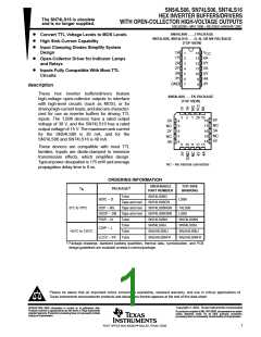
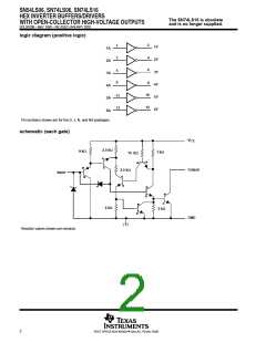
SN54LS06, SN74LS06, SN74LS16
HEX INVERTER BUFFERS/DRIVERS
WITH OPEN-COLLECTOR HIGH-VOLTAGE OUTPUTS
The SN74LS16 is obsolete
and is no longer supplied.
SDLS020B – MAY 1990 – REVISED JANUARY 2002
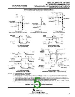
†
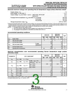
absolute maximum ratings over operating free-air temperature range (unless otherwise noted)
Supply voltage, V
. . . . . . . . . . . . . . . . . . . . . . . . . . . . . . . . . . . . . . . . . . . . . . . . . . . . . . . . . . . . . . . . . . . . . . . . 7 V
CC
Input voltage, V (see Note 1) . . . . . . . . . . . . . . . . . . . . . . . . . . . . . . . . . . . . . . . . . . . . . . . . . . . . . . . . . . . . . . . 5.5 V
I
Output voltage, V (see Notes 1 and 2): SN54LS06, SN74LS06 . . . . . . . . . . . . . . . . . . . . . . . . . . . . . . . . 30 V
O
SN74LS16 . . . . . . . . . . . . . . . . . . . . . . . . . . . . . . . . . . . . . . . . . . . 15 V
Package thermal impedance, θ (see Note 3): D package . . . . . . . . . . . . . . . . . . . . . . . . . . . . . . . . . . . 86°C/W
JA
N package . . . . . . . . . . . . . . . . . . . . . . . . . . . . . . . . . . . 80°C/W
NS package . . . . . . . . . . . . . . . . . . . . . . . . . . . . . . . . . 76°C/W
Storage temperature range, T
. . . . . . . . . . . . . . . . . . . . . . . . . . . . . . . . . . . . . . . . . . . . . . . . . . . –65°C to 150°C
stg
†
Stresses beyond those listed under “absolute maximum ratings” may cause permanent damage to the device. These are stress ratings only, and
functional operation of the device at these or any other conditions beyond those indicated under “recommended operating conditions” is not
implied. Exposure to absolute-maximum-rated conditions for extended periods may affect device reliability.
NOTES: 1. All voltage values are with respect to GND.
2. This is the maximum voltage that should be applied to any output when it is in the off state.
3. The package thermal impedance is calculated in accordance with JESD 51-7.
recommended operating conditions
SN74LS06
SN74LS16
SN54LS06
UNIT
MIN NOM
MAX
MIN NOM
MAX
V
V
V
Supply voltage
4.5
2
5
5.5
4.75
2
5
5.25
V
V
CC
IH
IL
High-level input voltage
Low-level input voltage
0.8
30
0.8
30
15
40
70
V
’LS06
V
V
OH
High-level output voltage
SN74LS16
V
I
Low-level output current
30
mA
°C
OL
T
A
Operating free-air temperature
–55
125
0
electrical characteristics over recommended operating free-air temperature range (unless
otherwise noted)
SN74LS06
SN54LS06
SN74LS16
‡
PARAMETER
UNIT
TEST CONDITIONS
I = –12 mA
§
§
MIN TYP
MAX
–1.5
0.25
MIN TYP
MAX
–1.5
0.25
0.25
0.4
V
IK
V
V
= MIN,
= MIN,
V
V
CC
I
’LS06,
V
OH
= 30 V
I
V
IL
= 0.8 V
OH
CC
SN74LS16,
V
OH
= 15 V
I
I
I
= 16 mA
= 30 mA
= 40 mA
0.25
0.4
0.7
0.25
OL
OL
OL
V
OL
V
CC
= MIN,
V
IH
= 2 V
V
0.7
1
I
I
I
I
I
V
CC
V
CC
V
CC
V
CC
V
CC
= MAX,
= MAX,
= MAX,
= MAX
= MAX
V = 7 V
I
1
20
mA
µA
I
V = 2.4 V
I
20
IH
V = 0.4 V
I
–0.2
18
–0.2
18
mA
mA
mA
IL
CCH
CCL
60
60
‡
§
For conditions shown as MIN or MAX, use the appropriate value specified under recommended operating conditions.
All typical values are at V = 5 V, and T = 25°C.
CC
A
3
POST OFFICE BOX 655303 • DALLAS, TEXAS 75265

 TI [ TEXAS INSTRUMENTS ]