Application Notes
PT4220/4240 Series
Table 2; UVLO Thresholds 4
Using the Remote On/Off with the PT4220/4240
Isolated 10W Excalibur DC/DC Converters
Series
Vin Range
UVLO Threshold
PT4220
PT4240
36 – 75V
18 – 36V
32V 2V
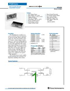
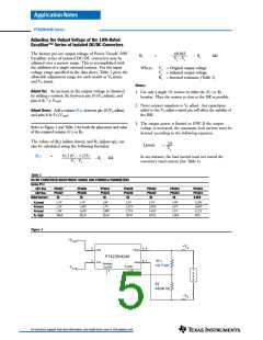
For applications requiring output voltage On/Off control,
the PT4220/4240 DC/DC converter series incorporates
a “Remote On/Off” control (pin 1). This feature can be
used to switch the module off without removing the
applied input source voltage.
15.8V 2V
Figure 1
5
8, 9
6, 7
+Vin
-Vin
+Vin
+Vout
+Vo
-Vo
The converter functions normally with Pin 1 open-circuit,
providing a regulated output voltage when a valid source
voltage is applied to +Vin (pin 5), with respect to –Vin
(pin 3). When a low-level 1 ground signal is applied to
pin 1, the converter output will be turned off.
PT4220/4240
3
-Vin
-Vout
Remote
On/Off
Vo (adj)
10
Note 1
1
Q1
BSS138
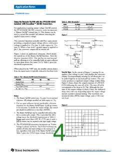
Figure 1 shows an application schematic, which details
the typical use of the Remote On/Off function. Note the
discrete transistor (Q1). The pin has its own internal
pull-up, allowing it to be controlled with an open-collector
or open-drain device (See notes 2 & 3). Table 1 gives the
threshold requirements.
1
=OFF
Note 1
Vdd
R1
10k
U1a
Note 1
When placed in the “Off” state, the standby current drawn
from the input source is typically reduced to less than 1mA.
Turn-On Time: In the circuit of Figure 1, turning Q1 on
applies a low-voltage to pin 1 and disables the converter
output. Correspondingly, turning Q1 off allows pin 1 to
be pulled high by an internal pull-up resistor. The con-
verter produces a regulated output voltage within 60ms.
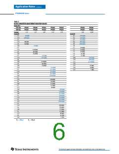
Figure 2 shows shows the output response of a PT4223
(5.0V) following the turn-off of Q1. The turn off of Q1
corresponds to the drop in Q1 Vgs. Although the rise-
time of the output voltage is short (<5ms), the indicated
delay time will vary depending upon the input voltage
and the module’s internal timing. The waveform was
measured with a 48Vdc input voltage, and a 1.4A resis-
tive load.
Table 1; Pin 1 Remote On/Off Control Parameters 1
Parameter
Min
Typ
Max
Enable (V
)
4.5V
—
—
—
—
IH
Disable (V
)
IL
0.8V
V
[Open-Circuit]
5.0V
—
o/c
[pin 1 at –V
I
—
–0.5mA
in
in]
Notes:
1. The Remote On/Off control uses –Vin (pin 3) as its ground
reference. All voltages specified are with respect to –Vin.
2. Use an open-collector device (preferably a discrete
transistor) for the Remote On/Off input. A pull-up resistor
isnotnecessary.Todisabletheoutputvoltage,thecontrol
pin should be pulled low to less than +0.8VDC.
Figure 2
3. The Remote On/Off pin may be controlled with devices that
have a totem-pole output. This is provided the drive
voltage meets the threshold requirements in Table1.
Do not apply more than +20V. If a TTL gate is used, a
pull-up resistor may be required to the logic supply voltage.
Vo (2V/Div)
Iin (0.2A/Div)
4. The PT4220/4240 converters incorporate an “Under-
Voltage Lockout” (UVLO). The UVLO will keep the
module off when the input voltage to the converter is
low, regardless of the state of the Remote On/Off control.
Table2 gives the UVLO input voltage thresholds.
Delay Time
Q1Vgs (10V/Div)
HORIZ SCALE: 10ms/Div
For technical support and more information, see inside back cover or visit www.ti.com

 TI [ TEXAS INSTRUMENTS ]