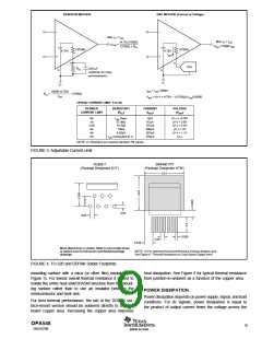
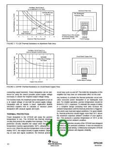
THERMAL RESISTANCE
vs ALUMINUM PLATE AREA
Aluminum Plate Area
Flat, Rectangular
18
16
14
12
10
8
Vertically Mounted
in Free Air
Aluminum Plate
θ
0.030in Al
0.050in Al
Aluminum
Plate Thickness
0.062in Al
5
Optional mica or film insulator
for electrical isolation. Adds
0
1
2
3
4
6
7
8
OPA548
TO220 Package
approximately 1°C/W.
Aluminum Plate Area (inches2)
FIGURE 5. TO-220 Thermal Resistance vs Aluminum Plate Area.
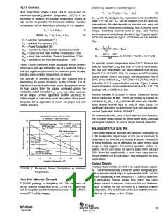
THERMAL RESISTANCE vs
CIRCUIT BOARD COPPER AREA
50
Circuit Board Copper Area
OPA548F
40
30
20
10
0
Surface Mount Package
1oz copper
OPA548
Surface-Mount Package
0
1
2
3
4
5
Copper Area (inches2)
FIGURE 6. DDPAK Thermal Resistance vs Circuit Board Copper Area.
conducting output transistor. Power dissipation can be mini-
mized by using the lowest possible power-supply voltage
necessary to assure the required output voltage swing.
circuit may cycle on and off. This limits the dissipation of the
amplifier but may have an undesirable effect on the load.
Any tendency to activate the thermal protection circuit indi-
cates excessive power dissipation or an inadequate heat
sink. For reliable operation, junction temperature should be
limited to 125°C, maximum. To estimate the margin of safety
in a complete design (including heat sink) increase the
ambient temperature until the thermal protection is triggered.
Use worst-case load and signal conditions. For good reliabil-
ity, thermal protection should trigger more than 35°C above
the maximum expected ambient condition of your applica-
tion. This produces a junction temperature of 125°C at the
maximum expected ambient condition.
For resistive loads, the maximum power dissipation occurs at
a dc output voltage of one-half the power-supply voltage.
Dissipation with ac signals is lower. Application Bulletin
SBOA022 explains how to calculate or measure power
dissipation with unusual signals and loads.
THERMAL PROTECTION
Power dissipated in the OPA548 will cause the junction
temperature to rise. The OPA548 has thermal shutdown
circuitry that protects the amplifier from damage. The thermal
protection circuitry disables the output when the junction
temperature reaches approximately 160°C, allowing the de-
vice to cool. When the junction temperature cools to approxi-
mately 140°C, the output circuitry is again enabled. Depend-
ing on load and signal conditions, the thermal protection
The internal protection circuitry of the OPA548 was designed
to protect against overload conditions. It was not intended to
replace proper heat sinking. Continuously running the OPA548
into thermal shutdown will degrade reliability.
OPA548
10
SBOS070B
www.ti.com

 TI [ TEXAS INSTRUMENTS ]