NE556, SA556, SE556
DUAL PRECISION TIMERS
SLFS023C – APRIL 1978 – REVISED DECEMBER 1999
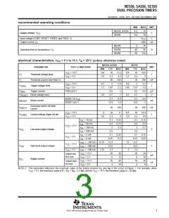
operating characteristics, V
= 5 V and 15 V
CC
NE556, SA556
SE556
TYP
0.5
TEST
CONDITIONS
PARAMETER
UNIT
†
MIN
TYP
1
MAX
MIN
MAX
§
§
§
Each timer, monostable
3
1.5
¶
‡
Each timer, astable
T
A
= 25°C
2.25%
±1
1.5%
±0.5
30
Initial error of timing interval
Timer 1 — Timer 2
Each timer, monostable
50
100
0.2
Temperature coefficient of
timing interval
¶
Each timer, astable
Timer 1 — Timer 2
T
A
= MIN to MAX
150
±10
0.1
90
ppm/°C
±10
0.05
0.15
±0.1
100
100
Each timer, monostable
0.5
Supply voltage sensitivity of
timing interval
¶
Each timer, astable
T
A
= 25°C
0.3
%/V
ns
Timer 1 — Timer 2
±0.2
100
100
Output pulse rise time
Output pulse fall time
300
300
200
200
C
T
A
= 15 pF,
= 25°C
L
†
‡
For conditions shown as MIN or MAX, use the appropriate value specified under recommended operating conditions.
Timing interval error is defined as the difference between the measured value and the average value of a random sample from each process
run.
§
¶
Values specified are for a device in a monostable circuit similar to Figure 2, with component values as follow: R = 2 kΩ to 100 kΩ, C = 0.1µF.
A
Values specified are for a device in an astable circuit similar to Figure 1, with component values as follow: R = 1 kΩ to 100 kΩ, C = 0.1µF.
A
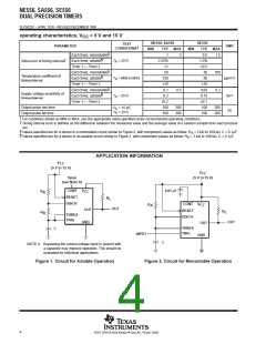
APPLICATION INFORMATION
V
CC
(5 V to 15 V)
V
CC
Open
(see Note A)
(5 V to 15 V)
CONT
RESET
DISCH
V
CC
0.01 µF
R
R
A
B
R
L
CONT
RESET
DISCH
V
R
CC
A
OUT
OUT
R
L
THRES
TRIG
GND
OUT
OUT
THRES
TRIG
C
INPUT
GND
C
NOTE A: Bypassing the control-voltage input to ground with
a capacitor may improve operation. This should be
evaluated for individual applications.
Figure 1. Circuit for Astable Operation
Figure 2. Circuit for Monostable Operation
4
POST OFFICE BOX 655303 • DALLAS, TEXAS 75265

 TI [ TEXAS INSTRUMENTS ]