MSP430G2x53
MSP430G2x13
www.ti.com
SLAS735A –APRIL 2011–REVISED MAY 2011
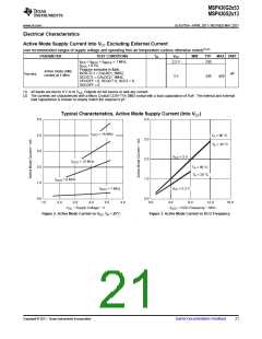
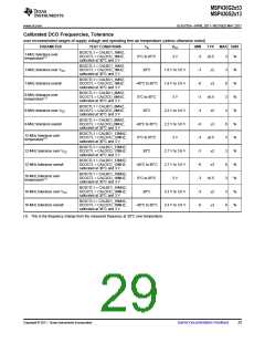
Pin-Oscillator Frequency – Ports Px
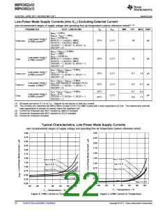
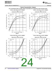
over recommended ranges of supply voltage and operating free-air temperature (unless otherwise noted)
PARAMETER
TEST CONDITIONS
VCC
MIN
TYP
1400
900
MAX UNIT
P1.y, CL = 10 pF, RL = 100 kΩ(1)(2)
P1.y, CL = 20 pF, RL = 100 kΩ(1)(2)
P2.0 to P2.5, CL = 10 pF, RL = 100 kΩ(1)(2)
P2.0 to P2.5, CL = 20 pF, RL = 100 kΩ(1)(2)
foP1.x
Port output oscillation frequency
3 V
kHz
1800
1000
foP2.x
foP2.6/7
foP3.x
Port output oscillation frequency
Port output oscillation frequency
Port output oscillation frequency
kHz
kHz
kHz
3 V
3 V
P2.6 and P2.7, CL = 20 pF, RL = 100
700
kΩ(1)(2)
P3.y, CL = 10 pF, RL = 100 kΩ(1)(2)
P3.y, CL = 20 pF, RL = 100 kΩ(1)(2)
1800
1000
(1) A resistive divider with two 0.5-kΩ resistors between VCC and VSS is used as load. The output is connected to the center tap of the
divider.
(2) The output voltage reaches at least 10% and 90% VCC at the specified toggle frequency.
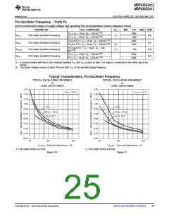
Typical Characteristics, Pin-Oscillator Frequency
TYPICAL OSCILLATING FREQUENCY
TYPICAL OSCILLATING FREQUENCY
vs
vs
LOAD CAPACITANCE
LOAD CAPACITANCE
1.50
1.35
1.20
1.05
0.90
0.75
0.60
0.45
0.30
0.15
0.00
1.50
1.35
1.20
1.05
0.90
0.75
0.60
0.45
0.30
0.15
0.00
V
CC
= 3.0 V
V
CC
= 2.2 V
P1.y
P1.y
P2.0 ... P2.5
P2.6, P2.7
P2.0 ... P2.5
P2.6, P2.7
10
50
100
10
50
100
C
LOAD
− External Capacitance − pF
C
LOAD
− External Capacitance − pF
A. One output active at a time.
A. One output active at a time.
Figure 10.
Figure 11.
Copyright © 2011, Texas Instruments Incorporated
Submit Documentation Feedback
25

 TI [ TEXAS INSTRUMENTS ]