www.ti.com
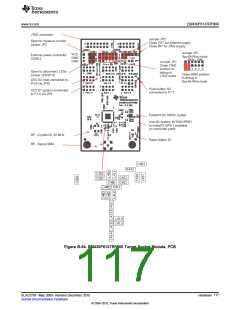
EM430F6137RF900
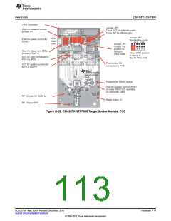
JTAG connector
Jumper JP2
Close EXT for external supply
Close INT for JTAG supply
Open to measure current
jumper JP3
Jumper JP1
Spy-Bi-Wire mode
VCC
GND
GND
External power connector
CON12
Jumper JP1
Close JTAG
position to
debug in
Open to disconnect LEDs
jumper JP5/JP10
Close SBW position
to debug in
Spy-Bi-Wire mode
JTAG mode
LED D2 (red) connected to
P3.6 via JP10
Push-button S2
connected to P1.7
LED D1 (green) connected
to P1.0 via JP5
Footprint for 32kHz crystal
Use 0Ω resistor for R541/R551
to makeP5.0/P5.1 available
on connector port5
RF - Crystal Q1 26 MHz
RF - Signal SMA
Reset button S1
C392
C422
Figure B-54. EM430F6137RF900 Target Socket Module, PCB
117
Hardware
SLAU278F–May 2009–Revised December 2010
Submit Documentation Feedback
© 2009–2010, Texas Instruments Incorporated

 TI [ TEXAS INSTRUMENTS ]