MC33063A
MC34063A
SLLS636L –DECEMBER 2004–REVISED DECEMBER 2009
www.ti.com
APPLICATION INFORMATION
CALCULATION
STEP UP
STEP DOWN
VOLTAGE INVERTING
Ť
Ť
Vout ) VF * Vin min
Vout ) VF
Vout ) VF
(
)
ton/toff
Vin min * Vsat * Vout
Vin * Vsat
Vin min * Vsat
(
)
(
)
1
f
1
f
1
f
(ton + toff
)
ton ) toff
ton ) toff
ton ) toff
t
t
t
on
on
on
toff
) 1
) 1
) 1
t
t
t
off
off
off
ǒ
Ǔ
ǒ
Ǔ
ǒ
Ǔ
ton ) toff * toff
ton ) toff * toff
ton ) toff * toff
ton
CT
*5
*5
*5
4 10
t
4 10
t
4 10
t
on
on
on
ton
toff
ton
toff
2Iout max
ǒ Ǔ
ǒ Ǔ
2Iout max
) 1
2Iout max
) 1
Ipk(switch)
(
)
(
)
(
)
0.3
0.3
Ipk switch
)
0.3
Ipk switch
RSC
Ipk switch
(
)
(
(
)
ǒV
Ǔ
ǒV
Ǔ
ǒV
Ǔ
) * Vsat
) * Vsat * Vout
) * Vsat
in min
(
(
(
in min
in min
t
t
t
L(min)
ǒ Ǔ ǒ
Ǔ ǒ Ǔ
(
)
(
)
(
)
on max
on max
on max
Ipk switch
Ipk switch
Ipk switch
( )
(
)
(
)
ǒ
Ǔ
Ioutton
Ipk switch ton ) toff
Ioutton
(
)
9
9
CO
Vripple pp
Vripple pp
8Vripple pp
(
)
(
)
(
)
R2
R1
R2
R1
R2
R1
1.25(1 )
)
1.25(1 )
)
*1.25(1 )
)
Vout
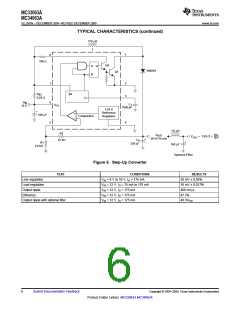
See Figure 6
See Figure 8
See Figure 10
Vsat = Saturation voltage of the output switch
VF = Forward voltage drop of the chosen output rectifier
The following power-supply parameters are set by the user:
Vin = Nominal input voltage
Vout = Desired output voltage
Iout = Desired output current
fmin = Minimum desired output switching frequency at the selected values of Vin and Iout
Vripple = Desired peak-to-peak output ripple voltage. The ripple voltage directly affects the line and load
regulation and, thus, must be considered. In practice, the actual capacitor value should be larger than the
calculated value, to account for the capacitor's equivalent series resistance and board layout.
10
Submit Documentation Feedback
Copyright © 2004–2009, Texas Instruments Incorporated
Product Folder Link(s): MC33063A MC34063A

 TI [ TEXAS INSTRUMENTS ]