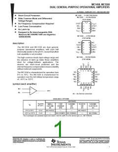
MC1458, MC1558
DUAL GENERAL-PURPOSE OPERATIONAL AMPLIFIERS
SLOS069A – FEBRUARY 1971 – REVISED MAY1999
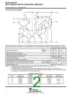
schematic (each amplifier)
V
CC +
IN –
IN +
OUT
V
CC –
absolute maximum ratings over operating free-air temperature range (unless otherwise noted)
MC1458
18
MC1558
22
UNIT
V
V
+
–
CC
Supply voltage (see Note 1)
V
–18
–22
CC
Differential input voltage (see Note 2)
±30
±30
V
V
Input voltage at either input (see Notes 1 and 3)
Duration of output short circuit (see Note 4)
Continuous total dissipation
±15
±15
unlimited
unlimited
See Dissipation Rating Table
Case temperature for 60 seconds: FK package
Lead temperature 1,6 mm (1/16 inch) from case for 60 seconds
Lead temperature 1,6 mm (1/16 inch) from case for 10 seconds
Storage temperature range
260
300
°C
°C
°C
°C
JG or U package
D or P package
260
65 to 150 –65 to 150
and V
NOTES: 1. All voltage values, unless otherwise noted, are with respect to the midpoint between V
2. Differential voltages are at IN+ with respect to IN–.
.
CC –
CC +
3. The magnitude of the input voltage must never exceed the magnitude of the supply voltage or 15 V, whichever is less.
4. The output can be shorted to ground or either power supply. For the MC1558 only, the unlimited duration of the short circuit applies
at (or below) 125°C case temperature or 70°C free-air temperature.
DISSIPATION RATING TABLE
T
≤ 25°C
DERATING
FACTOR
DERATE
ABOVE T
T
= 70°C
T = 125°C
A
POWER RATING
A
A
PACKAGE
POWER RATING
POWER RATING
A
D
FK
JG
P
680 mW
680 mW
680 mW
680 mW
675 mW
5.8 mW/°C
11.0 mW/°C
8.4 mW/°C
8.0 mW/°C
5.4 mW/°C
33°C
88°C
69°C
65°C
25°C
464 mW
880 mW
672 mW
640 mW
432 mW
—
275 mW
210 mW
—
U
135 mW
2
POST OFFICE BOX 655303 • DALLAS, TEXAS 75265

 TI [ TEXAS INSTRUMENTS ]