www.ti.com
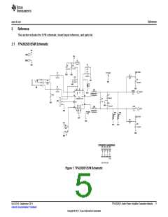
Operation
NOTE: The TPA2025D1 has an auto pass-through mode. Under normal operation (EN = HIGH), the
boost converter automatically turns off if no audio signal is present at one of the inputs (IN+
or IN-).
2.2 Boost Settings
The default voltage for the boost converter is 5.9 V (unloaded) and cannot be changed. If no audio signal
is present, the boost converter is automatically disabled. Once the audio signal is present at IN+ and IN-,
the boost converter enables automatically, when the output signal exceeds 2 VPEAK
.
2.2.1
Boost Terms
The following is a list of terms and definitions:
CMIN
Minimum boost capacitance required for a given ripple voltage on PVOUT (PVDD)
Boost inductor
L
fboost
Switching frequency of the boost converter
IPVDD
Current pulled by the class-D amplifier from the boost converter
Current pulled by the class-D amplifier from the boost converter
Current through the boost inductor.
IPVDD
IL
PVDD (PVOUT)
Supply voltage for the class-D amplifier (Voltage generated by the boost converter
output)
VBAT (VDD)
Supply voltage to the TPA2025D1 (Supply voltage to the EVM).
Ripple current through the inductor.
ΔIL
ΔV
Ripple voltage on PVOUT (PVDD) due to capacitance
2.2.2
Changing the Boost Inductor
Working inductance decreases as inductor current increases. If the drop in working inductance is severe
enough, it may cause the boost converter to become unstable, or cause the TPA2025D1 to reach its
current limit at a lower output power than expected. Inductor vendors specify currents at which inductor
values decrease by a specific percentage. This can vary by 10% to 35%. Inductance is also affected by dc
current and temperature.
Inductor current rating is determined by the requirements of the load. The inductance is determined by two
factors: the minimum value required for stability and the maximum ripple current permitted in the
application.
Use Equation 1 to determine the required current rating. Equation 1 shows the approximate relationship
between the average inductor current, IL, to the load current, load voltage, and input voltage (IPVDD
,
PVOUT, and VBAT, respectively.) Insert IPVDD, PVDD, and VBAT into Equation 1 to solve for IL. The
inductor must maintain at least 90% of its initial inductance value at this current.
PVDD
æ
ç
è
ö
÷
ø
IL = IPVDD
´
VBAT ´ 0.8
(1)
The minimum working inductance is 1.3 μH. A lower value may cause instability.
Ripple current, ΔIL, is peak-to-peak variation in inductor current. Smaller ripple current reduces core losses
in the inductor as well as the potential for EMI. Use Equation 2 to determine the value of the inductor, L.
Equation 2 shows the relationships among inductance L, VBAT, PVDD, the switching frequency, fboost, and
ΔIL. Insert the maximum acceptable ripple current into Equation 2 to solve for L.
VBAT ´ (PVDD - VBAT)
L =
ΔIL ´ fBOOST ´ PVDD
(2)
3
SLOU310–September 2011
TPA2025D1 Audio Power Amplifier Evaluation Module
Submit Documentation Feedback
Copyright © 2011, Texas Instruments Incorporated

 TI [ TEXAS INSTRUMENTS ]