LM79M05, LM79M12, LM79M15
www.ti.com
SNOS553D –MAY 1998–REVISED APRIL 2013
DESIGN CONSIDERATIONS
The LM79MXX fixed voltage regulator series have thermal-overload protection from excessive power, internal
short-circuit protection which limits the circuit's maximum current, and output transistor safe-area compensation
for reducing the output current as the voltage across the pass transistor is increased.
Although the internal power dissipation is limited, the junction temperature must be kept below the maximum
specified temperature in order to meet data sheet specifications. To calculate the maximum junction temperature
or heat sink required, the following thermal resistance values should be used:
Package
θJC
(°C/W)
3
θJA
(°C/W)
40
TO-220
(1)
θCA = θCS+θSA
Solving for TJ:
TJ
= TA+ PD (θJC+θCA) or
= TA=+ PDθJA(Without a Heat Sink)
Where
TJ
= Junction Temperature
TA
= Ambient Temperature
PD
= Power Dissipation
θJC
= Junction-to-Case Thermal Resistance
θCA = Case-to-Ambient Thermal Resistance
θCS = Case-to-Heat Sink Thermal Resistance
θSA = Heat Sink-to-Ambient Thermal Resistance
θJA
= Junction-to-Ambient Thermal Resistance
Typical Applications
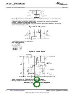
Bypass capacitors are necessary for stable operation of the LM79MXX series of regulators over the input voltage
and output current ranges. Output bypass capacitors will improve the transient response of the regulator.
The bypass capacitors (2.2μF on the input, 1.0μF on the output), should be ceramic or solid tantalum which have
good high frequency characteristics. If aluminum electrolytics are used, their values should be 10μF or larger.
The bypass capacitors should be mounted with the shortest leads, and if possible, directly across the regulator
terminals.
Copyright © 1998–2013, Texas Instruments Incorporated
Submit Documentation Feedback
7
Product Folder Links: LM79M05 LM79M12 LM79M15

 TI [ TEXAS INSTRUMENTS ]